

2022 Town of Aurora Accessibility Design Standards
Acknowledgements
December, 2021
Re: Town of Aurora Accessibility Design Standards
The Town of Aurora is pleased to present the 2022 Town of Aurora Accessibility Design Standards. This updated document outlines Town-wide standards that build a universally-designed and accessible community for residents, visitors and employees.
What’s new
- changes to the Ontario Building Code 2022 ;
- the Accessibility for Ontarians with Disabilities Act’s (AODA) Accessibility Standards for the Design of Public Spaces (O. Reg. 413/12);
- larger dimensional requirements of wheelchairs and scooters;
- requirements related to sensory disability (i.e. vision and hearing loss); and
- additional sections: therapeutic pools, spray pads, wayfinding and information systems.
These standards are applied to all new and/or renovated Town owned, leased or operated facilities. In addition to our municipal facilities, we encourage their use throughout the community.
We would like to thank and recognize contributions of:
- The City of London for its generous permission to use the City of London 2015 Facility Accessibility Design Standards (2015) as the basis for this standard.
- The Town of Aurora’s Accessibility Advisory Committee, Accessibility Advisor and all involved municipal staff.
- Mr. Bob Topping and other staff of DesignABLE Environments Inc. who have been instrumental in creating this resource.


These standards are a key component of the Town’s vision for accessibility to make Aurora a great place to live, work, travel and play for everyone. They reflect our corporate values of Trust, Quality and Excellence and ensure Aurora is a place where everyone belongs.
Mateusz Zawada,
Accessibility Advisor

Table of Contents
2.0 - Glossary and Definitions
4.1.1 - Space and Reach Requirements
4.1.2 - Ground and Floor Surfaces
4.1.3 - Protruding and Overhead Objects
4.1.4 - Accessible Routes, Paths and Corridors
4.1.5 - Entrances
4.1.6 - Doors
4.1.7 - Gates, Turnstiles and Openings
4.1.8 - Windows, Glazed Screens and Sidelights
4.1.9 - Ramps
4.1.10 - Curb Ramps
4.1.11 - Stairs
4.1.12 - Handrails
4.1.13 - Elevators
4.1.14 - Platform Lifts
4.2.1 - Toilet Facilities
4.2.2 - Toilet Stalls
4.2.3 - Toilets
4.2.4 - Lavatories
4.2.5 - Urinals
4.2.6 - Washroom Accessories
4.2.7 - Universal Washrooms
4.2.8 - Showers
4.2.9 - Grab Bars
4.3.1 - Drinking Fountains
4.3.2 - Viewing Positions
4.3.3 - Elevated Platforms
4.3.4 - Change/Dressing Rooms
4.3.5 - Offices, Work Areas and Meeting Rooms
4.3.6 - Waiting and Queuing Areas
4.3.7 - Tables, Counters and Work Surfaces
4.3.8 - Information, Reception and Service Counters
4.3.9 - Storage, Shelving and Display Units
4.3.10 - Lockers and Baggage Storage
4.3.11 - Roof-top Patios, Balconies, Porches, Terraces and Patios
4.3.12 - Parking
4.3.13 - Passenger Loading Zones
4.3.14 - Landscaping Materials and Plantings
4.3.15 - Benches
4.3.16 - Public Use Eating Areas
4.3.17 - Streetscapes
4.3.18 - Kitchens and Kitchenettes
4.3.19 - Service Animal Relief Areas
4.4.1 - Emergency Exits, Fire Evacuation and Areas of Rescue Assistance
4.4.2 - Controls and Operating Mechanisms
4.4.3 - Vending and Ticketing Machines
4.4.4 - Visual Alarms
4.4.5 - Public Telephones
4.4.6 - Assistive Listening Systems
4.4.7 - Signage
4.4.8 - Detectable Warning Surfaces
4.4.9 - Public Address Systems
4.4.10 - Information Systems
4.4.11 - Card Access, Safety and Security Systems
4.4.12 - Glare and Light Sources
4.4.13 - Lighting
4.4.14 - Materials and Finishes
4.4.15 - Texture and Colour
4.4.16 - Acoustics
4.4.17 - Pedestrian Signals
4.5 - Facility-Specific Requirements
4.5.1 - Arenas, Halls and Other Indoor Recreational Facilities
4.5.2 - Outdoor Recreational Facilities
4.5.3 - Swimming Pools, Therapeutic Pools/Public Spas and Spray Pads
4.5.4 - Cafeterias
4.5.5 - Churches, Chapels and Other Places of Worship
4.5.6 - Libraries
4.5.7 - Business, Mercantile and Civic
4.5.8 - Fire Stations
4.5.9 - Training and Teaching Spaces
4.5.10 - Laboratories
4.5.11 - Child Care/Minding
4.6 - Maintenance and Operations
A - Universal Design Principles and Guidelines
B - Wayfinding
C - Accessibility Standards Checklist
D - Change Order Form
E - Slip Resistance of Materials
F - Additional Resources
The following tables identify the design elements that must be considered for exterior and interior projects.
General Characteristics
For all aspects of projects, the following general characteristic elements (where provided) must be reviewed for compliance with the standard.
4.1 Access and Circulation
4.1.1 Space and Reach Requirements
4.1.2 Ground and Floor Surfaces
4.1.3 Protruding and Overhead Objects
4.1.4 Accessible Routes, Paths and Corridors
4.1.5 Entrances
4.1.6 Doors
4.1.9 Ramps
4.1.11 Stairs
4.1.12 Handrails
4.3 Other Amenities
4.3.3 Elevated Platforms
4.3.11 Roof-top Patios, Balconies, Porches, Terraces And Patios
4.3.15 Benches
4.3.16 Public Use Eating Areas
4.4 Systems and Controls
4.4.7 Signage
4.4.8 Detectable Warning Surfaces
4.4.13 Lighting
4.4.14 Materials and Finishes
4.4.15 Texture and Colour
4.5 Facility-Specific Requirements
4.5.3 Swimming Pools, Therapeutic Pools/Public Spas and Spray Pads
Site Characteristics
When designing the exterior and site, the following site characteristic elements (where provided) must be reviewed for compliance with the standard (in addition to the general characteristics listed above).
4.1 Access and Circulation
4.1.10 Curb Ramps
4.3 Other Amenities
4.3.12 Parking
4.3.13 Passenger Loading Zones
4.3.14 Landscaping Materials and Plantings
4.3.17 Streetscapes
4.3.19 Service Animal Relief Areas
4.4 Systems and Controls
4.4.17 Pedestrian Signals
4.5 Facility-Specific Requirements
4.5.2 Outdoor Recreational Facilities
Building Characteristics
When designing the interior the following building characteristic elements (where provided) must be reviewed for compliance with the standard (in addition to the general characteristics listed on the above).
4.1 Access and Circulation
4.1.5 Entrances
4.1.6 Doors
4.1.7 Gates, Turnstiles and Openings
4.1.8 Windows, Glazed Screens and Sidelights
4.1.13 Elevators
4.1.14 Platform Lifts
4.2 Washroom Facilities
4.2.1 Toilet Facilities
4.2.2 Toilet Stalls
4.2.3 Toilets
4.2.4 Lavatories
4.2.5 Urinals
4.2.6 Washroom Accessories
4.2.7 Individual Washrooms
4.2.8 Showers
4.2.9 Grab Bars
4.3 Other Amenities
4.3.1 Drinking Fountains
4.3.2 Viewing Positions
4.3.4 Dressing Rooms
4.3.5 Offices, Work Areas and Meeting Rooms
4.3.6 Waiting and Queuing Areas
4.3.7 Tables, Counters and Work Surfaces
4.3.8 Information, Reception and Service Counters
4.3.9 Storage, Shelving and Display Units
4.3.10 Lockers and Baggage Storage
4.3.18 Kitchens and Kitchenettes
4.4 Systems and Controls
4.4.1 Emergency Exits, Fire Evacuation and Areas of Rescue Assistance
4.4.2 Controls and Operating Mechanisms
4.4.3 Vending and Ticketing Machines
4.4.4 Visual Alarms
4.4.5 Public Telephones
4.4.6 Assistive Listening Systems
4.4.9 Public Address Systems
4.4.10 Information Systems
4.4.11 Card Access, Safety and Security Systems
4.4.12 Glare and Light Sources
4.4.16 Acoustics
4.5 Facility-Specific Requirements
4.5.1 Arenas, Halls and Other Indoor Recreational Facilities
4.5.3 Swimming Pools, Therapeutic Pools/Public Spas and Spray Pads
4.5.4 Cafeterias
4.5.5 Churches, Chapels and Other Places of Worship
4.5.6 Libraries
4.5.7 Business, Mercantile and Civic
4.5.8 Fire Stations
4.5.9 Training and Teaching Spaces
4.5.10 Laboratories
4.5.11 Child Care/Minding
2022 Town of Aurora Accessibility Design Standards
1.0 - Introduction
This standard addresses accessibility requirements for the design and construction of new facilities, as well as the retrofit, alteration or addition to existing facilities, owned, leased or operated by the Town of Aurora. This standard particularly addresses the needs of persons with disabilities, including, but not limited to, persons using a mobility aid, hearing loss, vision loss/no vision, cognitive disability, persons who are deaf-blind and persons with limited stamina and/or dexterity.
This standard is intended to encompass the intent of the Ontario Human Rights Code, in terms of respecting the dignity of persons with disabilities. “The phrase ‘respects their dignity’ means to act in a manner which recognizes the privacy, confidentiality, comfort, autonomy and self-esteem of persons with disabilities, which maximizes their inclusion and which promotes full participation in society.” (Ontario Human Rights Commission)
This standard incorporates the belief in universal design that recognizes the broad diversity of people who use facilities. Universal design is defined as: “The design of products and environments to be usable by all people, to the greatest extent possible, without the need for adaptation or specialized design.”
The universal design philosophy is structured around the seven Design Principles listed below. (Refer to Appendix A for further information on the universal design principles and their guidelines.)
This standard reflects minimum dimensional criteria required for adult persons. Prior to the design stage of a project, special consideration should be given to the function of the facility and the patrons who will use it. A review and upgrade of this standard may be required in some instances, particularly if a facility is designed primarily for the use of a particular type of user, such as children or older persons.
Where conflicts exist between scoping and/or dimensional requirements of this standard and legislation enacted by the federal or provincial governments’, the most accommodating requirements shall apply (i.e. the requirement(s) that will result in the most accommodating environment but never less than the minimum requirements of the current Ontario Building Code).
The Facilities and Code Review & Inspection division of the Town of Aurora shall review and/or update this standard as necessary, to reflect technological advancement and new construction practices, as well as changes to the barrier-free design requirements of various codes and standards such as the Ontario Building Code (OBC), Accessibility for Ontarians with Disabilities Act (AODA), and the CSA Standard B651 - Accessible Design for the Built Environment.
This standard recognizes the concept of equivalent facilitation as a means to encourage new and innovative design ideas and solutions. Departures from particular technical and scoping requirements of this standard by the use of other designs and technologies are encouraged when the alternatives will provide substantially equivalent or greater access to the usability of the element and/or facility. Design departures from information provided and referenced in this standard should be carefully assessed to determine the validity of the application and may require review by the Accessibility Advisor.
Dimensions used in this standard are in metric units. Nearest imperial equivalent dimensions are in parentheses.
For the purposes of this standard, words and terms in bold have their meanings defined in Section 2.0.
The Town of Aurora encourages all users of this standard to provide feedback, as well as to make proposals for changes, additions and/or deletions. A proposed Change Order Form is included in Appendix B of this standard.
The Principles of Universal Design
1. Equitable Use:
The design is useful and marketable to people with diverse abilities.
2. Flexibility in Use:
The design accommodates a wide range of individual preferences and abilities.
3. Simple and Intuitive Use:
Use of the design is easy to understand, regardless of the user’s experience, knowledge, language skills, or current concentration level.
4. Perceptible Information:
The design communicates necessary information effectively to the user, regardless of ambient conditions or the user’s sensory abilities.
5. Tolerance for Error:
The design minimizes hazards and the adverse consequences of accidental or unintended actions.
6. Low Physical Effort:
The design can be used efficiently and comfortably with a minimum of fatigue.
7. Size and Space for Approach and Use:
Appropriate size and space are provided for approach, reach, manipulation and use, regardless of user’s body position, size, posture or mobility.
The Principles of Universal Design
© NC State University, The Center for Universal Design
2.0 - Glossary and Definitions
Graphic Conventions
Dimensions that are not marked maximum or minimum are absolute, unless otherwise indicated.
General Terminology
comply with Meet one or more specifications of this standard.
if … then Denotes a specification that applies only when the conditions described are present.
may Denotes an option or alternative.
shall Denotes a mandatory specification or requirement.
should Denotes an advisory specification or recommendation.
Definitions
Access aisle: An accessible pedestrian space between elements, such as parking spaces, seating and desks, that provides clearances appropriate for the use of the elements.
Accessible: Describes a site, building, facility or portion thereof that complies with this standard.
Accessible element: An element specified by this standard (for example, telephone, controls etc.).
Accessible route: A continuous unobstructed path connecting accessible elements and spaces of a facility. Interior accessible routes may include corridors, floors, ramps, elevators, platform lifts and clear floor spaces at fixtures. Exterior accessible routes may include parking access aisles, curb ramps, crosswalks at vehicular ways, walkways, ramps and platform lifts.
Accessible space: Space that complies with this standard.
Adaptable: The ability of a certain building space or element, such as kitchen counters, sinks, and grab bars, to be added or altered so as to accommodate the needs of individuals with or without disabilities or to accommodate the needs of persons with different types or degrees of disabilities.
Adaptable seating: A fixed seat in an assembly occupancy located adjacent to an access aisle with a removable, foldable or no armrest to allow a person to transfer from one side into the fixed seating area from the access aisle.
Addition: An expansion, extension, or increase in the gross floor area of a facility.
Administrative Authority: A governmental agency that adopts or enforces regulations and guidelines for the design, construction, or alteration of buildings and facilities.
Alteration: A change to a facility that affects or could affect the usability of the facility or part thereof. Alterations include, but are not limited to, remodelling, renovation, retrofitting, rehabilitation, reconstruction, historic restoration, resurfacing of circulation paths or vehicular ways, changes or rearrangement of the structural parts or elements, and changes or rearrangement in the plan configuration of walls and full-height partitions. Normal maintenance, painting or wallpapering, or changes to mechanical or electrical systems are not alterations, unless they affect the usability of the building.
Area of rescue assistance: An area which has direct access to an exit, where people who are unable to use stairs may remain temporarily in safety to await further instructions or assistance during emergency evacuation.
Assembly area: A room or space accommodating a group of individuals for recreational, educational, political, social, civic or amusement purposes, or for the consumption of food and drink.
Assistive device: See Mobility assistive device.
Attic or roof space: The uninhabitable portion of a building or structure which is immediately below the roof and wholly or partially within the roof framing.
Automatic door: A door equipped with a power-operated mechanism and controls that open and close the door automatically upon receipt of a momentary actuating signal. The switch that begins the automatic cycle may be a photoelectric device, floor mat, or manual switch. (See Power-assisted door)
Board room or Conference room or Meeting room: A room used for meetings, which accommodates six or more people.
Boarding pier: A portion of a pier where a boat is temporarily secured for the purpose of embarking or disembarking.
Boat launch ramp: A sloped surface designed for launching and retrieving trailered boats and other water craft to and from a body of water.
Boat slip: That portion of a pier, main pier, finger pier, or float where a boat is moored for the purpose of berthing, embarking, or disembarking.
Building: A structure occupying an area greater than ten square metres, consisting of a wall, roof and floor or any of them, or a structural system serving the function thereof, including all plumbing, fixtures and service systems appurtenant thereto; or a structure occupying an area of ten square metres or less that contains plumbing, including the plumbing appurtenant thereto; or structures designated in the Ontario Building Code.
Circulation path: An exterior or interior way of passage from one place to another for pedestrians, including, but not limited to, walkways, hallways, courtyards, stairways, and stair landings.
Clear: Unobstructed.
Clear floor space: The minimum unobstructed floor or ground space required to accommodate a single, stationary wheelchair, scooter or other mobility assistive device, including the user.
Closed-circuit telephone: A telephone with dedicated line(s), such as a house phone, courtesy phone or phone that must be used to gain entrance to a facility.
Common use: Refers to those interior and exterior rooms, spaces or elements that are made available for the use of a restricted group of people (for example, occupants of a homeless shelter, the occupants of an office building, or the guests of such occupants).
Cross slope: The slope that is perpendicular to the direction of travel. (See Running slope)
Crosswalk: a) That part of a highway at an intersection that is included within the connections of the lateral lines of the sidewalk on opposite sides of the highway measured from the curbs or, in the absence of curbs, from the edges of the roadway; or
b) Any portion of a roadway at an intersection or elsewhere distinctly indicated for pedestrian crossing by signs or by lines or other markings on the surface. (from the Traffic By-law 555-2000)
Curb ramp: A short ramp cutting through a curb or built up to a curb.
Depressed curb: A continuous area where a curb is lowered to the same level as the adjacent roadway, resulting in a seamless transition between a pedestrian walkway and a vehicular way.
Detectable warning surfaces: A standardized surface feature built into or applied to walking surfaces or other elements to warn persons with vision loss/no vision of hazards on a circulation path. These are also known as: “Tactile Ground Indicators (TGI)” or “Tactile Warning Surface Indicators (TWSI)”.
Disability: Any restriction or lack of ability to perform an activity in the manner or within the range considered normal for a human being.
Driveway: An internal roadway, that is not a street, private road, CEC - private road, internal road or lane, which provides vehicular access from a street, private road, CEC - private road, to parking or loading spaces.
Dwelling unit: A single unit which provides a kitchen or food preparation area, in addition to rooms and spaces for living, bathing, sleeping, and the like. Dwelling units include a single family home or a townhouse used as a transient group home; an apartment building used as a shelter; guestrooms in a hotel that provide sleeping accommodations and food preparation areas; and other similar facilities used on a transient basis. For the purposes of these guidelines, use of the term “Dwelling Unit” does not imply the unit is used as a residence.
Egress, means of: A continuous and unobstructed way of exit travel from any point in a facility to a public way. A means of egress comprises vertical and horizontal travel and may include intervening room spaces, doorways, hallways, corridors, passageways, balconies, ramps, stairs, enclosures, lobbies, horizontal exits, courts and yards. An accessible means of egress is one that complies with this standard and does not include stairs, steps or escalators. Areas of rescue assistance, protected lobbies or protected elevators may be included as part of an accessible means of egress.
Element: An architectural or mechanical component of a building, facility, space or site (e.g., telephone, curb ramp, door, drinking fountain, seating or water closet).
Entrance: Any access point into a building or facility used for the purposes of entering. An entrance includes the approach walkway, the vertical access leading to the entrance platform, the entrance platform itself, vestibules (if provided), the entry door(s) or gate(s), and the hardware of the entry door(s) or gate(s).
Elevated play component: A play component that is approached above or below grade and that is part of a composite play structure consisting of two or more play components attached or functionally linked to create an integrated unit providing more than one play activity.
Facility or Facilities: All or any portion of buildings, structures, site improvements, complexes, equipment, roads, walkways, passageways, parks, parking lots or other real or personal property located on a site.
Gangway: A variable sloped pedestrian walkway that links a fixed structure or land with a floating structure. Gangways which connect to vessels are not included.
Ground floor: Any occupiable floor less than one storey above or below grade with direct access to grade. A facility always has at least one ground floor and may have more than one ground floor, as where a split-level entrance has been provided or where a facility is built into a hillside.
Ground level play component: A play component that is approached and exited at the ground level.
Guard: A safety railing used as a barrier to prevent encroachment or accidental falling from heights.
Handrail: A component which is normally grasped by hand for support at stairways and other places where needed for the safety of pedestrians.
Heritage Facility: A facility or portions thereof designated under the Ontario Heritage Act, or identified in the inventory of heritage resources for the Town of Aurora. (See Public Heritage Facility)
Impairment: Any loss or abnormality of psychological, physiological or anatomical structure or function.
Landscaped area: Any outdoor area on a lot, located at grade, including the landscaped buffer area, that is suitable for the growth and maintenance of grass, flowers, shrubs, trees and other landscape features, and may include walkways, berms, retaining walls and outdoor amenity areas, but shall not include, driveways, aisles, ramps or internal roads, parking areas whether surfaced or not, curbs, any open space beneath or within any building, structure or part thereof, or any exterior garbage storage or handling area.
Marked crossing: A crosswalk or other identified path intended for pedestrian use in crossing a vehicular way.
Mezzanine or Mezzanine floor: That portion of a storey which is an intermediate floor level, placed within the storey and having occupiable space above and below its floor.
Mobility assistive device: A mobility assistive device as defined in section 2 of Ontario Regulation 191/11 (Integrated Accessibility standards) made under the Accessibility for Ontarians with Disabilities Act, 2005.
Multifamily dwelling: Any building containing more than two dwelling units.
Multi-use trail: A multi-use trail managed by a public authority. A multi-use trail means that part of a highway, boulevard or city/town right-of-way that is designated by authorized signs for shared use by cyclists, pedestrians and in-line skaters, in accordance with Traffic By-law Schedule 35 or the Parks By-law. (128-09). A multi-use trail shall be designed, constructed and maintained to minimize impacts on the natural environment and may include mitigative structures, such as raised boardwalks and footbridges. See also Recreational trail.
Occupiable: A room or enclosed space designed for human occupancy in which individuals congregate for amusement, educational or similar purposes, or in which occupants are engaged at labour, and which is equipped with means of egress, light and ventilation.
Open space: Large-scale tracts of land without visible evidence of residential, commercial or industrial development. These areas may be privately or publicly owned and are generally left in a natural state and not programmed for active recreation. The benefits of open lands typically extend beyond the immediate area and usually provide community-wide benefits.
Operable portion: A part of a piece of equipment or appliance used to insert or withdraw objects, or to activate, deactivate, or adjust the equipment or appliance (for example, coin slot, push button, handle).
Park: Land that is privately or publicly held that has been developed for multiple recreational and leisure-time uses. This land benefits the entire community and balances the demands of the public for outdoor recreational facilities and other amenities, such as recreational trails, picnic areas, playgrounds, water features, and spaces for free play and leisure.
Parking space for persons with disabilities: An unobstructed rectangular area exclusive of any aisle or driveway for the temporary parking of a motor vehicle, for persons with disabilities.
Path: See Path of travel.
Path of travel: A continuous, unobstructed way of pedestrian passage, including but not limited to walkways and sidewalks, curb ramps and other interior or exterior pedestrian ramps, clear floor paths through lobbies, corridors, rooms, parking access aisles, elevators and lifts, or a combination of these elements.
Pathway: See Path of Travel.
Play Area: A portion of a site containing play components designed and constructed for children.
Play Equipment/Component: An element intended to generate specific opportunities for play, socialization, or learning. Play components may be manufactured or natural, and may be stand alone or part of a composite play structure.
Power-assisted door: A door used for human passage that has a mechanism that helps to open the door or relieves the opening resistance of a door, upon the activation of a switch or a continued force applied to the door itself.
Private open space: Privately owned land areas within a subdivision, generally smaller in scale than open space, which have been left free from structures, parking lots and roads. These types of areas generally benefit only the residents or employees of the particular subdivision and usually remain in private ownership.
Public Heritage Facility: A facility or portions thereof designated under the Ontario Heritage Act, or identified in the inventory of heritage resources for the Town of Aurora and that is open and accessible to the public. (See Heritage Facility)
Public use: Describes interior or exterior rooms or spaces that are made available to the general public. Public use may be provided at a facility that is privately or publicly owned.
Ramp: A walking surface which has a running slope greater than 1:20 (5%).
Recreational Trail: Public pedestrian trails that are intended for recreational and leisure purposes. Note that a multi-use trail is one type of recreational trail and must adhere to all recreational trail requirements in addition to those specific to multi-use trails. (Refer also to definition of Multi-Use Trail)
Retrofit: See Alteration.
Running slope: The slope that is parallel to the direction of travel. (See Cross slope)
Service entrance: An entrance intended primarily for delivery of goods or services and not intended for use by the public.
Service room: A room provided in a building to contain equipment associated with building services.
Service space: A space provided in a facility to facilitate or conceal the installation of facility service facilities such as chutes, ducts, pipes, shafts or wires.
Signage: Displayed verbal, symbolic, tactile and pictorial information.
Site: A parcel of land bound by a property line or a designated portion of a public right-of-way.
Site improvement: Landscaping, paving for pedestrian and vehicular ways, outdoor lighting, recreational facilities added to a site.
Sleeping accommodations: Rooms in which people sleep, for example, a dormitory.
Space: A definable area (e.g. room, toilet room, hall, assembly area, entrance, storage room, alcove, courtyard or lobby).
Storey: The portion of a building, structure or part thereof, that is situated between the top of any floor and the top of the floor next above it, and if there is no floor above it, that portion between the top of the floor and the ceiling above it. If such portion of a building does not include occupiable space, it is not considered a storey for the purposes of this standard. There may be more than one floor level within a storey, as in the case of a mezzanine or mezzanines.
Structural frame: The columns and the girders, beams, trusses and spandrels having direct connection to the columns and all other members which are essential to the stability of the building as a whole.
TDD (Telecommunication Device for the Deaf): See Text telephone.
TTY (Teletypewriter): See Text telephone.
Tactile: Describes an object that can be perceived using the sense of touch.
Technically infeasible: Means, with respect to an alteration of a building or a facility, that it has little likelihood of being accomplished, because:
- existing structural conditions would require moving or altering a load-bearing member which is an essential part of the structural frame; or
- other existing physical or site constraints prohibit modification or addition of necessary elements, spaces or features which are in full and strict compliance with the minimum requirements for new construction.
Temporary structure: A facility that is not of permanent construction but that is extensively used, or is essential for public use for a period of time. Examples of temporary facilities covered by this standard include, but are not limited to, reviewing stands, bleacher areas, temporary kiosks, temporary health screening services or temporary safe pedestrian passageways around a construction site. Structures and equipment directly associated with the actual processes of construction, such as scaffolding, bridging, materials hoists, or construction trailers, are not included.
Text telephone (TTY): Machinery or equipment that employs interactive text-based communication through the transmission of coded signals across the standard telephone network. Text telephones can include, for example, devices known as TDDs (telecommunication display devices or telecommunication devices for deaf persons) or computers with special modems. Text telephones are also called TTYs, an abbreviation for teletypewriter.
Transfer device: Equipment designed to facilitate the transfer of a person from a wheelchair or other mobility device to and from an amusement ride seat.
Universal Design Principles: The principles by which the environment can be designed in order to accommodate the abilities of all.
Vehicular way: A route intended for vehicular traffic, such as a street, driveway or parking lot, within the boundary of the site.
Walkway: An exterior pathway with a prepared surface intended for pedestrian use, including general pedestrian areas, such as plazas and courts, within the boundary of the site.
3.0 - Scope and Application
General
- The requirements of this standard shall be
- mandatory for all newly constructed and retrofitted facilities owned, leased or operated by the Town of Aurora; and
- encouraged for all other facilities, whether new or retrofitted.
- Exceptions: This standard does not apply to
- residential occupancies;
- buildings of Group F Division 1 occupancy, as defined by the Ontario Building Code (latest edition with all amendments); and
- buildings which are not intended to be occupied on a daily or full-time basis, including, but not limited to, automatic telephone exchanges, pump houses and substations.
General Application
- All areas of newly designed or newly constructed facilities and altered portions of existing facilities shall comply with Sections 4.1 to 4.4 of this standard, unless otherwise provided in this section or as modified in Section 4.5, Facility-Specific Requirements.
- Exceptions: The requirements of Sections 4.1 to 4.4 do not apply to
- service rooms
- elevator machine rooms
- janitor rooms
- service spaces
- crawl spaces
- attic or roof spaces.
Application Based on Facility Use
- The specific facility types listed in Section 4.5 shall, in addition to all of the provisions specified in Section 4.1 to 4.4, comply with the additional design requirements specified in Section 4.5.
- Where a facility contains more than one use covered by a special application section, each portion shall comply with the requirements for that section in addition to all other general provisions.
Work Areas and Employee-Designated Areas
- All facilities shall be accessible for employees, as well as patrons/users. All areas intended for use by employees shall be designed and constructed to comply with this standard.
Temporary Facilities
- This standard applies to temporary facilities, as well as permanent facilities.
Retrofitting, Alterations and Additions
- Each addition to an existing facility shall be regarded as an alteration.
- Each space or element added to the existing facility shall comply with the applicable provision(s) of this standard.
- Except where the provision of accessible features is technically infeasible, no alteration shall decrease or have the effect of decreasing accessibility or usability of an existing facility to below the requirements for new construction at the time of alteration.
- If existing elements, spaces or common areas are altered, then each such altered element/space/feature/area shall comply with all applicable provisions. If the applicable provision for new construction requires that an element/space/feature/area be on an accessible route and the altered element/space/feature/area is not on an accessible route, this route shall be altered to become accessible.
- If alterations of single elements, when considered together, amount to an alteration of a room or space in a facility, the entire space shall be made accessible.
- No alteration of an existing element, space or area of a facility shall impose a requirement for greater accessibility than that which would be required for new construction.
- If an escalator or stairs are proposed as a means of access where none existed previously, and major structural modifications are necessary for such installations, then a means of accessible access shall also be provided.
- If a planned alteration entails alterations to an entrance, and the facility has an accessible entrance, the entrance being altered is required to be accessible.
- If the alteration work is limited solely to the electrical, mechanical or plumbing system, or to hazardous material abatement, or to automatic sprinkler retrofitting, and does not involve the alteration of any elements or spaces required to be accessible under these guidelines, then this standard does not apply (except for alarms, public telephones and assistive listening systems).
- An alteration that affects the usability of or access to an area containing a primary function shall be made to ensure that, to the maximum extent feasible, the route of travel to the altered area, the restrooms, telephones and drinking fountains serving the altered area are readily accessible to and usable by individuals with disabilities.
- Where the provision of accessible features is technically infeasible, and the standard allows a reduction of manoeuvring space from the requirements for new construction, the reduced dimensions are minimums. Where possible, larger manoeuvring spaces must be provided.
Heritage Facilities
- This standard will apply to alterations to a Heritage Facility, however, under the Ontario Human Rights Code, there are allowances for modification to the defining features of a Heritage Facility which are deemed to alter the essential nature or substantially affect the viability of the enterprise. Public Heritage Facilities should be assessed for compliance to accessibility standards on an individual basis, to determine the most effective and least disruptive means of retrofit, where required. Consider the following general guidelines:
- Facilities and/or areas that are generally used independently by the public and have undergone extensive modernization should be permanently and fully accessible. This includes parking areas, reception areas, washrooms, food service areas and gift shops. It can also include walkways and garden areas. If accessibility is limited by non-heritage elements, those elements should be revised.
- Facilities and/or areas which are used only by guided tour groups, through which assistance could easily be provided to open doors or to place a temporary ramp, could remain as existing or with minor temporary modifications.
- It is desirable to provide a complete experience of a Public Heritage Facility. If an accessible area or areas can be provided to fully experience a given site or facility context, access to the entire site or facility is not necessary.
- Access to above-grade and below-grade areas is not necessary if the context of those areas can be adequately provided on the accessible floor level.
- If retrofit for accessibility of a main public entrance in a Heritage Facility would substantially threaten or destroy attributes identified in the heritage designation by-law, access shall be provided at an alternative entrance with directional signs at the main public entrance. The accessible entrance should have a notification system (if not generally used by the public) and remote monitoring (if security is an issue).
- Safe egress from a Heritage Facility is required.
Equivalent Facilitation
- In a retrofit situation where the requirements of a section of this standard are technically infeasible to implement, equivalent facilitation may be proposed.
- Equivalent facilitation proposals shall be referred to the Manager of Code Review and Inspection of the Town of Aurora for review and approval on an individual basis.
Implementation
- The Facilities and Code Review & Inspection division of the Town of Aurora, other Town departments, as well as contracted consulting firms shall be responsible for the application of the 2022 Town of Aurora Accessibility Design Standards when designing and administering all construction and renovation projects associated with new facilities, as well as the retrofit, alteration or addition to existing facilities, owned, leased or operated by the Town of Aurora.
- Designing and constructing to this standard shall be included as a mandatory requirement in all Town of Aurora requests for proposals, tender documents and construction contracts.
Enforcement
- The Facilities and Code Review & Inspection division of the Town of Aurora and other Town departments, through the project management function, shall ensure compliance to this standard during the preplanning, design, construction documents preparation and contracts administrative phase.
4.0 - Design Standards
- All areas of newly designed or newly constructed facilities and altered portions of existing facilities shall comply with this section, unless otherwise provided in Section 3.0.
- Exceptions: This standard does not apply to
- residential occupancies;
- buildings of Group F Division 1 occupancy, as defined by the Ontario Building Code (latest edition with all amendments); and
- buildings which are not intended to be occupied on a daily or full-time basis, including, but not limited to, automatic telephone exchanges, pump houses and substations.
- The requirements of this section apply to all areas of a facility except
- service rooms
- elevator machine rooms
- janitor rooms
- service spaces
- crawl spaces
- attic or roof spaces
The design elements in these standards are organized by: - Access and Circulation;
- Washroom Facilities;
- Other Amenities;
- Systems and Controls; and
- Facility-Specific Requirements.
4.1 - Access and Circulation
4.1.1 - Space and Reach Requirements
4.1.1 - Rationale
- The dimensions and manoeuvring characteristics of wheelchairs, scooters and other mobility devices are as varied as the people who use them. Traditionally, accessibility standards have taken a conservative approach to wheelchair manoeuvrability, reflecting the needs of a physically strong individual using a manual wheelchair. Such an approach excludes the many users without such a degree of strength or those using a larger mobility device. This standard more accurately reflects the vast array of equipment that is used by individuals to access and use facilities, as well as the diverse range of user ability. This standard incorporates more generous space requirements, particularly related to the dynamic movement of people using wheelchairs, scooters or other assistive devices.
4.1.1 - Application
- Space and reach range provisions for persons who use wheelchairs, scooters and other mobility devices shall comply with this section.
4.1.1 - Design Requirements
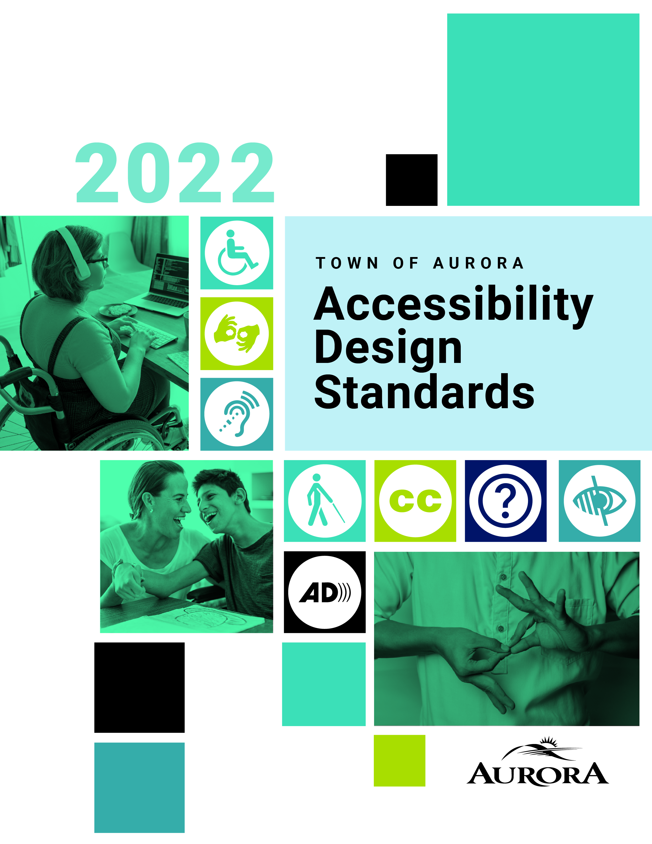
- The space required for a wheelchair to make a 360-degree turn is a clear floor space of 2440 mm (96 in.) in diameter (Figure 4.1.1.1) or for a 180-degree turn, as shown in Figure 4.1.1.2.
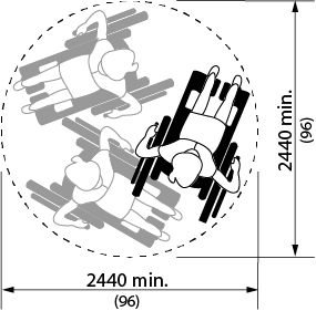
Figure 4.1.1.1 360 degree Turning Space
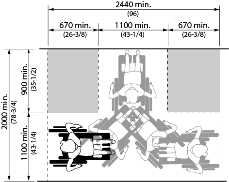
Figure 4.1.1.2 180 degree Turning Space
- The minimum clear floor space or ground space necessary to accommodate the largest dimensional requirement of a single, stationary wheelchair or scooter and its' occupant shall be 760 mm (30 in.) x 1370 mm (54 in.). (Refer to Figures 4.1.1.5 and 4.1.1.6)
Figure 4.1.1.5 Clear Floor Space for Wheelchair
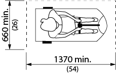
Figure 4.1.1.6 Clear Floor Space for Scooter
- The minimum clear floor space or ground space for wheelchairs or scooters may be positioned for forward or parallel approach to an object.
- Clear floor space or ground space for wheelchairs may be part of the knee space required under some objects.
- One full, unobstructed side of the clear floor space or ground space for a wheelchair or scooter shall adjoin or overlap an accessible route or adjoin another wheelchair clear floor space. If a clear floor space is located in an alcove or otherwise confined on all or part of three sides, additional manoeuvring clearances shall be provided as shown in Figures 4.1.1.3, 4.1.1.4, 4.1.1.7 and 4.1.1.8.
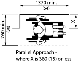
Figure 4.1.1.3 Clearances at Alcove
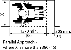
Figure 4.1.1.4 Clearances at Alcove
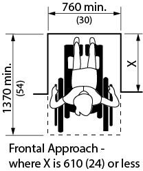
Figure 4.1.1.7 Clearances at Alcove
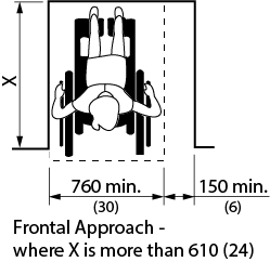
Figure 4.1.1.8 Clearances at Alcove
- The surface of clear floor or ground spaces for wheelchairs and scooters shall comply with 4.1.2.
- If the clear floor space only allows forward approach to an object, the maximum high forward reach allowed shall be 1200 mm (47 in.). The minimum low forward reach is 400 mm (15-3/4 in.). Refer to Figure 4.1.1.11. If the high forward reach is over an obstruction, reach and clearances shall be as shown in Figures 4.1.1.12 and 4.1.1.13.
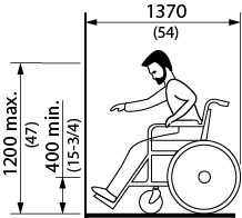
Figure 4.1.1.11 Forward Reach
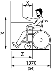
Figure 4.1.1.12 Forward Reach over an Obstruction
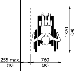
Figure 4.1.1.13 Side Reach - Maximum Distance to Wheelchair
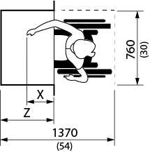
Figure 4.1.1.14 Forward Reach over an Obstruction
- Note: In Diagrams 4.1.1.12 and 4.1.1.14, X shall be less than or equal to 635 mm (25 in.): Z shall be greater than or equal to X.
When X is less than 510 mm (20 in.), then Y shall be 1220 mm (48 in.) maximum.
When X is 510 to 635 mm (20 to 25 in.), then Y shall be 1120 mm (44 in.) maximum. - If the clear floor space allows parallel approach to an object, the maximum high side reach allowed shall be 1370 mm (54 in.) and the low side reach no less than 230 mm (9 in.) above the floor. Refer to Figure 4.1.1.9. If the side reach is over an obstruction, the reach and clearances shall be as shown in Figure 4.1.1.9 and 4.1.1.13. Notwithstanding these requirements, the Ontario Building Code requires all controls for the operation of facility services to be no more than 1200 mm (47 in.) above the floor for thermostats or manual pull station and 900 - 1100 mm (35-1/2 - 43-1/4 in.) for all other controls including typical light switches.
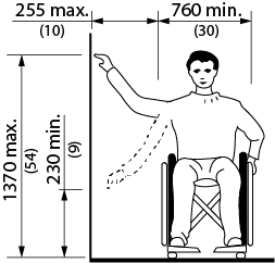
Figure 4.1.1.9 Side Reach
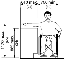
Figure 4.1.1.10 Side Reach over an Obstruction
4.1.2 - Ground and Floor Surfaces
4.1.2 - Rationale
- Design decisions related to ground and floor surfaces will influence every person who enters the building. Irregular surfaces, such as cobblestones or pea-gravel finished concrete, are difficult for both walking and pushing a wheelchair. Slippery surfaces are hazardous to all individuals and especially hazardous for seniors and others who may not be sure-footed.
- Glare from polished floor surfaces can be uncomfortable for all users and can be a particular obstacle to persons with vision loss/no vision by obscuring important orientation and safety features. Pronounced colour contrast between walls and floor finishes may be helpful for persons with vision loss/no vision, as are changes in colour/texture where a change in level or function occurs.
- Patterned floors should be avoided, as they can create visual confusion.
- Thick pile carpeting makes pushing a wheelchair very difficult. Small and uneven changes in floor level represent a further barrier to using a wheelchair but also present a tripping hazard to ambulatory persons.
- Openings in any ground or floor surface such as grates or grilles can catch canes or wheelchair wheels.
4.1.2 - Application
- Ground and floor surfaces along all routes generally used by staff and public and within all areas generally used by staff and public shall comply with this section.
4.1.2 - Design Requirements
- Ground and floor surfaces shall be stable, firm, slip-resistant and glare-free.
- Changes in level, except for elevators and other elevating devices, shall conform to Table 4.1.2.
| Vertical rise | Edge Treatment |
|---|---|
| 0 to 6 mm (0 - 1/4 in.) | May be vertical |
| 6.1 to 13 mm (9/32 - 1/2 in.) | Bevel, maximum slope 1:2 |
| Over 13 mm (over 1/2 in.) | Treat as a sloped floor, ramp, or curb ramp. |

Figure 4.1.2.1a Changes in Level
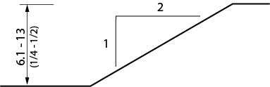
Figure 4.1.2.1b Changes in Level
- Carpets or carpet tile shall
- be securely fixed;
- have a firm cushion, pad or backing, where used;
- have a level loop, textured loop, level cut pile, or level cut/uncut pile texture with a maximum pad and pile height of 13 mm (1/2 in.); and
- have exposed edges fastened to floor surfaces with trim conforming to Table 4.1.2.
- Gratings located in walking surfaces shall
- have spaces not greater than 13 mm (1/2 in.) wide in one direction; and
- be placed so that the long dimension is across the dominant direction of travel.
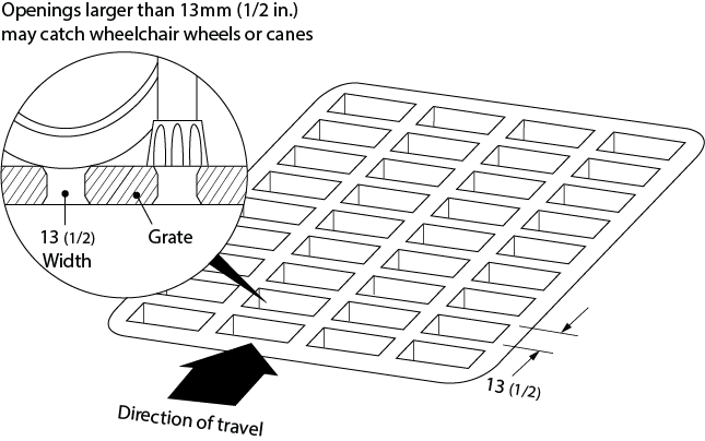
Figure 4.1.2.2 Grills and Gratings
4.1.2 - Related Sections
4.1.4 Accessible Routes, Paths and Corridors
4.4.8 Detectable Warning Surfaces
4.4.14 Materials and Finishes
4.4.15 Texture and Colour
4.1.3 - Protruding and Overhead Objects
4.1.3 - Rationale
- The creation of pathways free from protruding objects or freestanding obstacles is important to all facility users. An object protruding from a wall above the detection range of a cane is dangerous for persons with vision loss/no vision or a pedestrian distracted by a conversation. The underside of stairways is a common overhead hazard. Temporary construction barriers can also be hazardous if their lower edge is too high to be detected by a person using a long white cane for mobility. Detectable warning surfaces around freestanding obstacles, such as light standards, are advantageous to anyone using a pathway.
4.1.3 - Application
- Protruding objects from a wall, ceiling or other location shall comply with this section.
4.1.3 - Design Requirements
- Objects protruding from walls with their leading edges between 680 mm (26-3/4 in.) and 2100 mm (82-3/4 in.) from the floor shall protrude not more than 100 mm (4 in.) into pedestrian areas, such as walkways, halls, corridors, passageways or aisles.
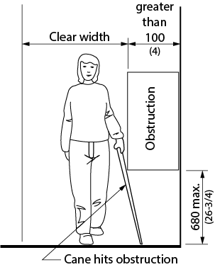
Figure 4.1.3.1 Limits of Protruding Objects between 680 and 2100 mm
- Objects attached to a wall with their leading edges at or below 680 mm (26-3/4 in.) from the floor may protrude any amount.
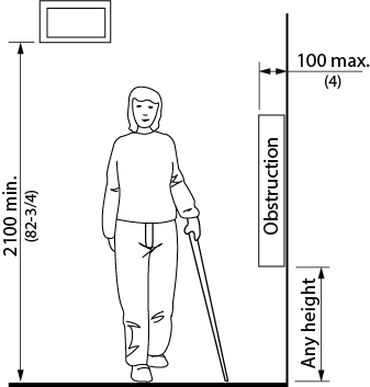
Figure 4.1.3.2 Limits of Protruding Objects at or below 680 mm
- Freestanding objects shall not have any overhang of more than 300 mm (11-3/4 in.) between 680 mm (26-3/4 in.) and 2100 mm (82-3/4 in.) from the ground or floor.
- The maximum height of the bottom edge of freestanding objects with a space of more than 300 mm (11-3/4 in.) between supports shall be 680 mm (26-3/4 in.) from the ground or floor.
- Protruding objects shall not reduce the clear width required for an accessible route or manoeuvring space.
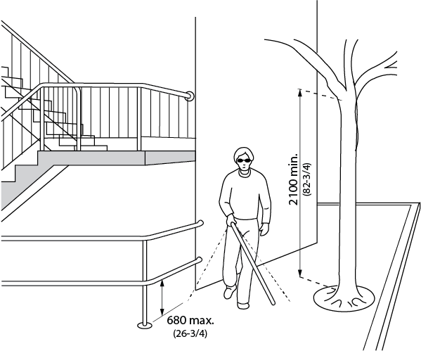
Figure 4.1.3.3 Overhead Obstructions
- The minimum clear headroom in pedestrian areas, such as walkways, halls, corridors, passageways, or aisles, shall be 2100 mm (82-3/4 in.).
- A detectable guard, guardrail or other barrier having its leading edge at or below 680 mm (26-3/4 in.) from the floor shall be provided where the headroom of an area adjoining an accessible route is reduced to less than 2100 mm (82-3/4 in.).
4.1.3 - Related Sections
4.1.4 Accessible Routes, Paths and Corridors
4.4.8 Detectable Warning Surfaces
4.4.14 Materials and Finishes
4.4.15 Texture and Colour
4.1.4 - Accessible Routes, Paths and Corridors
4.1.4 - Rationale
- Routes of travel through a facility should address the full range of individuals that may use them. They must provide the clear width necessary for persons using wheelchairs or scooters, those pushing strollers or those travelling in pairs. Consideration should be given to the width and maneuverability of mobility devices, such as wheelchairs and scooters. While a corridor may be wide enough for a person to drive a scooter in a straight line, it may not be possible to make a turn around a corner. The preferred minimum width for primary accessible routes is 1830 mm (72 in.).
- Strong colour contrasts and/or tactile pathways set into floors may be used to assist individuals with vision loss/no vision to negotiate an environment.
- Edge protection that guards a change in level is an important safety feature for all users.
4.1.4 - Application
- Wherever possible, all routes, paths and corridors shall comply with this section.
- At least one accessible route complying with this section shall be provided within the boundary of the site from accessible parking spaces, passenger-loading zones (if provided), and public streets or sidewalks to the accessible facility entrance they serve. The accessible route shall, to the maximum extent feasible, coincide with the route for the general public.
- At least one accessible route shall connect accessible buildings, facilities, elements and spaces that are on the same site. It is preferable to have all routes accessible.
- Except where essential obstructions in a work area would make an accessible route hazardous, an accessible route shall connect accessible entrances with all accessible spaces and elements within the facility. An accessible route complying with this section shall be provided within all normally occupiable floor areas.
- Exceptions: The provision of an accessible route does not apply
- to service rooms;
- to elevator machine rooms;
- to janitor rooms;
- to service spaces;
- to crawl spaces;
- to attic or roof spaces;
- to high-hazard industrial occupancies;
- within portions of a floor area with fixed seats in an assembly occupancy where these portions are not part of an accessible route to spaces designated for wheelchair use; or
- within a suite of residential occupancy.
- Accessible routes are permitted to include ramps, curb ramps, stairs (alongside ramps), elevators or other elevating devices (as permitted in 4.1.14) where a difference in elevation exists.
- A walkway or pedestrian bridge connecting two barrier-free storeys in different buildings shall form part of an accessible route and shall comply with this section.
4.1.4 - Design Requirements
- The minimum clear width of an accessible route shall be 1100 mm (43-1/4 in.) except
- at doors - refer to 4.1.6;
- where additional manoeuvring space is required at doorways (See 4.1.6);
- at U-turns around obstacles less than 1220 mm (48 in.) wide, it shall be 1220 mm (48 in.);
- for exterior routes, it shall be 1500 mm (59 in.). This can be reduced to 1220 (48 in.) where the route connects to a curb ramp to serve as a turning space at the top of the ramp;
- where space is required for two wheelchairs to pass, it shall be 1830 mm (72 in.); and
- at secondary circulation routes within open office areas, where systems-furniture work station clusters are used, it shall be 920 mm (36 in.).
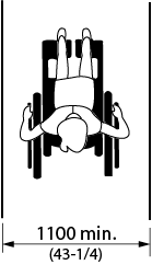
Figure 4.1.4.2a Minimum Width of Interior Accessible Route
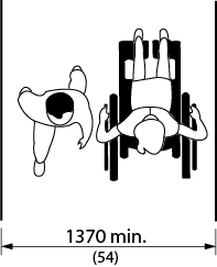
Figure 4.1.4.2b Minimum Width of Interior Accessible Route
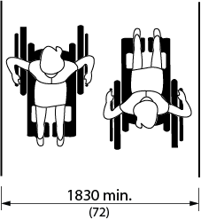
Figure 4.1.4.2c Minimum Width of Secondary Access Route within Open Office Areas
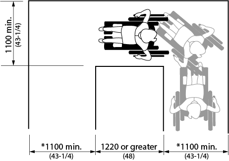
Figure 4.1.4.3 Turn Around an Obstacle greater than 1200 wide
(Dimensions marked * to be increased to 1220 mm (48 in.) at exterior routes)
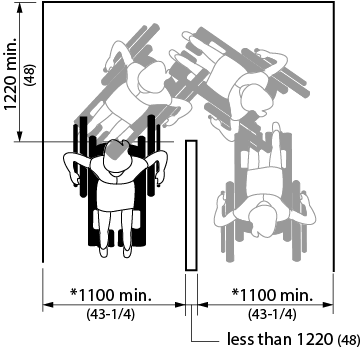
Figure 4.1.4.4 Turn Around an Obstacle less than 1200 wide
(Dimensions marked * to be increased to 1220 mm (48 in.) at exterior routes)
- Where accessible routes less than 2000 mm (78-3/4 in.) wide terminates at a dead end, a turn space in compliance with 4.1.1 shall be provided at the dead end.
- Entrance to an exterior path of travel must provide a minimum clearance of 950 mm (37-1/2 in.) (whether entrance includes gate, offset gates, bollard, or other entrance design).
- Accessible routes shall
- Every accessible route less than 1830 mm (72 in.) wide shall be provided with an unobstructed passing space of not less than 1830 mm (72 in.) in width and 1830 mm (72 in.) in length, located not more than 30 meters (98 ft. 5 in.) apart.
- Except at stairs and at elevated platforms such as performance areas or loading docks, where the edge(s) of an accessible route, path or corridor is not level with the adjacent surface, the edge(s) shall be protected
- by a colour contrasting curb of at least 75 mm (3 in.) high where the change in level is between 200 mm (7-7/8 in.) and 600 mm (23-5/8 in.); and
- by a guard which meets the requirements of the Ontario Building Code where the change in level is greater than 600 mm (23-5/8 in.).
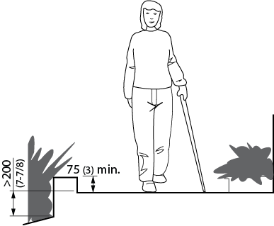
Figure 4.1.4.1 Edge Protection
- Where there is a change in direction along an accessible route and the intended destination of the route is not evident, directional signage shall be provided.
- All portions of an accessible route shall be equipped to provide a minimum level of illumination of 50 lux (4.6 ft-candles).
- Exception: In outdoor park settings where routes are not normally illuminated, additional illumination is not required.
- Accessible routes shall incorporate level rest areas spaced no more than 30 metres (98ft. - 5in.) apart.
- Recreational trails need flexibility in locations of rest areas (i.e. 30 to 90 m (98 ft. - 5 in. to 295 ft. - 3 in.) apart.)
- Consultation with the Municipal Accessibility Advisory Comittee, the public and persons with disabilities regarding the design and location of rest areas along exterior paths of travel must be undertaken as required by the AODA Accessibility Standard for the Design of Public Spaces.
- Designated areas for snow piling to be provided at exterior accessible routes, located away from pedestrian routes.
4.1.4 - Related Sections
4.1.2 Ground and Floor Surfaces
4.1.7 Gates, Turnstiles and Openings
4.1.9 Ramps
4.1.10 Curb Ramps
4.2.3 Elevated Platforms
4.4.7 Signage
4.4.8 Detectable Warning Surfaces
4.4.12 Glare and Light Sources
4.4.13 Lighting
4.4.14 Materials and Finishes
4.4.15 Texture and Colour
4.1.5 - Entrances
4.1.5 - Rationale
- Design decisions concerning entrances will have an immediate impact on the independence and dignity of everyone entering a facility. Entrances that address the full range of individuals using the facility promote a spirit of inclusion that separate accessible entrances do not. Features such as canopies can limit the influence of weather conditions on this already busy area and also make an entrance more obvious to a person with a cognitive disability or someone unfamiliar with the facility.
4.1.5 - Application
- All entrances used by staff and/or the public shall be accessible and comply with this section. In a retrofit situation where it is technically infeasible to make all staff and public entrances accessible, at least 50% of all staff and public entrances shall be accessible and comply with this section. In a retrofit situation where it is technically infeasible to make all public entrances accessible, the primary entrances used by staff and the public shall be accessible.
- Accessible public entrances must be provided in a number at least equivalent to the number of exits required by the Ontario Building Code. (This paragraph does not require an increase in the total number of public entrances required for a facility.)
- An accessible public entrance must be provided to each tenancy in a facility.
- If direct access is provided for pedestrians from an enclosed parking garage to a facility, at least one direct entrance from the parking garage to the facility must be accessible.
- If access is provided for pedestrians from a pedestrian tunnel, walkway or pedestrian bridge, at least one entrance to the facility from each tunnel, walkway or bridge must be accessible.
- If the only entrance to a facility or tenancy is a service entrance, that entrance shall be accessible.
- Entrances which are not accessible shall have directional signage complying with 4.4.7 which indicates the nearest accessible entrance.
- Accessible entrances shall be identified with signage complying with applicable provisions of 4.4.7.
- Accessible entrances shall be served by an accessible route in compliance with 4.1.4.
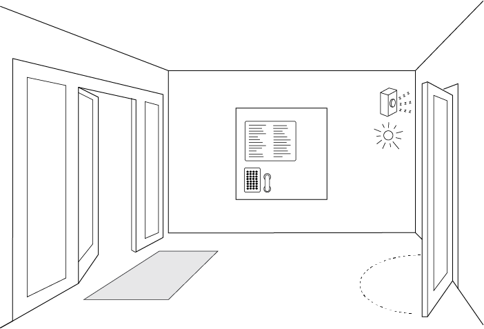
Figure 4.1.5.1 Entrance Vestibule
4.1.5 - Related Sections
4.1.1 Space and Reach Requirements
4.1.6 Doors
4.1.7 Gates, Turnstiles and Openings
4.1.8 Windows, Glazed Screens and Sidelights
4.4.2 Controls and Operating Mechanisms
4.4.7 Signage
4.4.10 Information Systems
4.4.11 Card Access, Safety and Security Systems
4.4.13 Lighting
4.1.6 - Doors
4.1.6 - Rationale
- Sufficiently wide doorways are advantageous to individuals using wheelchairs or scooters, pushing strollers, or making a delivery. However, a raised threshold at the base of the door could impede any one of these same individuals. This same group, with the addition of children, seniors or even someone carrying packages, would have difficulty opening a heavy door and would benefit from some form of automatic door opener. Where permitted and where feasible, entrances without doors are preferred.
- Independent use of doors is desirable. Reliance on assistance from others to open doors is not an accessible or dignified solution.
- Careful thought to the direction of the door swing can enhance the usability and limit the hazard to other pedestrians. Sliding doors can be easier for some individuals to operate, and can also require less wheelchair manoeuvring space. Doors that require two hands to operate are not considered to be accessible. Revolving doors are not accessible for persons using wheelchairs and strollers (unless they are very large revolving doors). Also, the coordination required to use such doors may be difficult for children or a person with a cognitive disability.
- Glazed doors can present a hazard to all individuals and especially those with vision loss/no vision. The inclusion of colour-contrast strips across the glass, mounted at eye level, as well as colour-contrasting door frames and door hardware, will increase the safety and visibility of a glazed door for a person with vision loss/no vision.
4.1.6 - Application
- All doors used by staff or the public shall comply with this section. In a retrofit situation where it is technically infeasible to make all doors accessible, at least one door at each accessible space shall comply with this section.
Exception: Doors not requiring full user passage, such as shallow closets, may have the clear opening reduced to 510 mm (20 in.) minimum. - Each door that is an element of an accessible route shall comply with this section.
- Each door required by 4.4.1 (Emergency Exits, Fire Evacuation and Areas of Rescue Assistance) shall comply with this section.
- Where a door system incorporates multiple door leafs at a single location, at least one of the door leafs shall comply with this section.
- Power operators shall be provided at the following door locations:
- entrances required by 4.1.5 including both inner and outer vestibule doors (where provided);
- washrooms that include an accessible toilet stall;
- universal washroom;
- change rooms that contain accessible toilet and shower facilities, as well as a private accessible change room; and
- intermediate doorways across primary circulation routes within a facility. Exception: Doors that are held-open using electromagnetic hold-open devices.
- Mats and mat sinkages at doors shall comply with this section.
- Revolving doors or turnstiles shall not be the only means of passage at an accessible entrance or along an accessible route. An accessible gate or door shall be provided adjacent to the turnstile or revolving door and shall be designated to facilitate the same use pattern.
- Frameless glass doors and/or sidelights shall not be used.
- Door hardware on all doors throughout a facility (not only those deemed accessible), shall comply with the door hardware requirements of this section.
4.1.6 - Design Requirements
- Where permitted, rooms without doors are preferred.
- Accessible doors shall be on an accessible route that complies with 4.1.4.
- The minimum clear opening of doorways shall be 950 mm (37-1/2 in.), measured between the face of the door and the opposite door stop with the door open 90 degrees. In a retrofit situation where it is technically infeasible to provide this clearance, the minimum clear opening of doorways may be reduced to 860 mm (33-3/4 in.)
- In Group B, Division 2 or 3 occupancy, the minimum clear width of doorways through which it is necessary to move a patient or resident in a bed shall be 1050 mm (41 in).
- Doors shall have level wheelchair-manoeuvring space on both sides of the door. Unless equipped with a power door operator, doors shall have a clear space beside the latch, as described in Table 4.1.6.
- Exception: The clear space is not required on the inactive side of a door, where access is provided from one side only - such as to a closet.
| Context | Floor space required (in mm) | ||
|---|---|---|---|
| Depth | Width | Space Beside Latch | |
| Side-hinged door - Front approach (Figure 4.1.6.3) | |||
| Pull side | 1525 (60 in.) | 1600 (63 in.) (*1525 (60 in.)) |
600 (23-5/8 in.) |
| Push side | 1370 (54 in.) | 1250 (49-1/4 in.) (*1220 (48 in.)) |
300 (11-3/4 in.) |
| Side-hinged door - Latch-side approach (Figure 4.1.6.2) | |||
| Pull side | 1370 (54 in.) (*1220 (48 in.)) |
1600 (63 in.) (*1525 (60 in.)) |
600 (23-5/8 in.) |
| Push side | 1370 (54 in.) (*1100 (43-1/4 in.)) |
1525 (60 in.) | 600 (23-5/8 in.) |
| Side-hinged door - Hinge-side approach (Figure 4.1.6.1) | |||
| Pull side | 2440 (96 in.) (*1525 (60 in.)) |
2440 (96 in.) (*1525 (60 in.)) |
600 (23-5/8 in.) |
| Push side | 1370 (54 in.) (*1100 (43-1/4 in.)) |
1830 (72 in.) | 450 (17-3/4 in.) |
| Sliding door (Figure 4.1.6.4) | |||
| Front Approach | 1370 (54 in.) | 1550 (61 in.) | 300 (11-3/4 in.) |
| Side Approach | 1370 (54 in.) (*1100 (43-1/4 in.)) |
2150 (84-5/8 in.) | 600 (23-5/8 in.) |
| Note: In retrofit situations where it is technically infeasible to provide the required clearances at doors, the clearances may be reduced as shown by the asterix (*). | |||
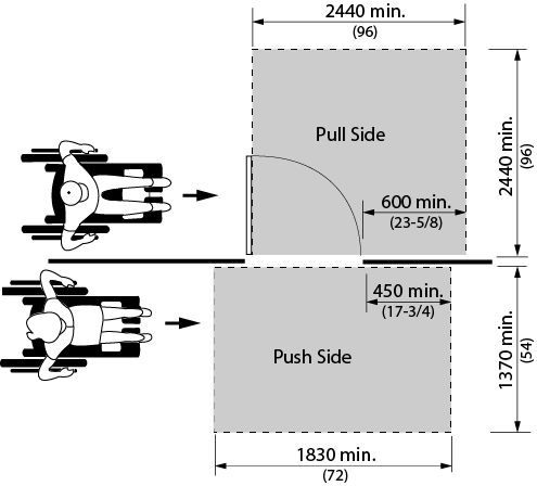
Figure 4.1.6.1 Hinge Side Approach at Hinged Doors
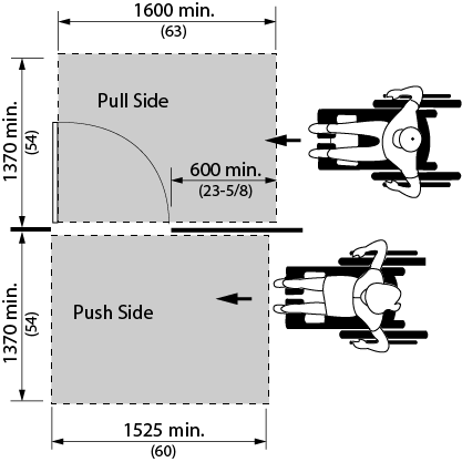
Figure 4.1.6.2 Latch Side Approach at Hinged Doors
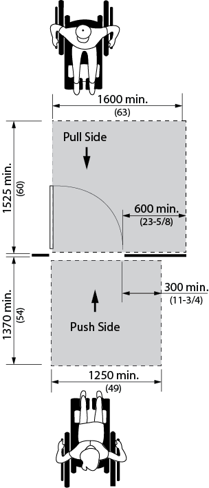
Figure 4.1.6.3 Front Approach at Hinged Doors
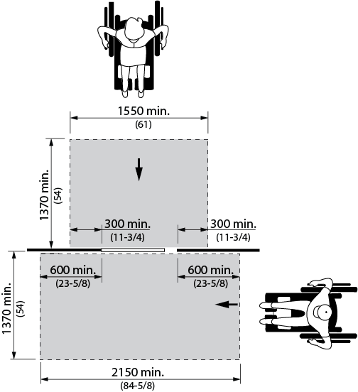
Figure 4.1.6.4 Front and Side Approach at Sliding Doors
- The required clear space beside the latch is to be unobstructed for the full height of the door.
- The minimum space between two hinged or pivoted doors in series shall be 1525 mm (60 in.), plus the width of any door swinging into the space.
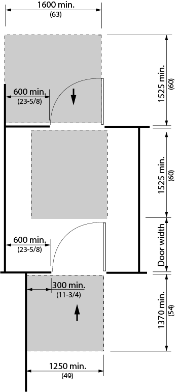
Figure 4.1.6.5 Manoeuvring Space at Doors in Series
- Where doors in a series do not align, a turn circle of at least 1525 mm (60 in.) shall be provided within the vestibule area, clear of any door swing. (See figure 4.1.6.6)
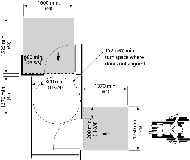
Figure 4.1.6.6 Manoeuvring Space at Doors in Series
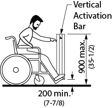
Figure 4.1.6.10 Vertical Bar Power Door Operator
- Thresholds shall
- be not more than 13 mm (1/2 in.) high; and
- where over 6 mm (1/4 in.) high, be bevelled at a maximum slope of 1:2 (50%).
- Door hardware (operating devices such as handles, pulls, latches, and locks) shall
- be operable by using a closed fist;
- not require fine finger control, tight grasping, pinching, or twisting of the wrist to operate; and
- be mounted between 900 mm (35-1/2 in.) and 1100 mm (43-1/4 in.) from the floor.
- Operating hardware on sliding doors shall be exposed and usable from both sides when sliding doors are fully open.
- The maximum door opening force for pushing or pulling open a door shall be no more than
- 38 N (8.5 lb.) for exterior hinged doors;
- 22 N (4.6 lb.) for interior hinged doors; and
- 22 N (4.6 lb.) for sliding or folding doors.
- Door closers shall be adjusted to the least pressure possible, but never more than the opening forces noted in this section.
- The sweep period of door closers shall be adjusted so that, from an open position of 90 degrees, the door will take not less than 3 seconds to move to a semi-closed position of approximately 12 degrees.
- Power-assisted swinging doors shall
- take not less than 3 seconds to move from the closed to the fully open position; and
- require a force of not more than 66 N (13.8 lb.) to stop door movement.
- Permanent mats and metal gratings at entrances and in vestibules shall be sunk level with the floor, so as not to create a tripping hazard.
- Occasional mats (e.g. runners used in bad weather) should be level with the floor surface and/or have a gently bevelled edge, so as not to create a tripping hazard.
- Where manually-activated power door operators are provided they shall
- be clearly visible;
- be located to allow persons to activate the opening of the door from either direction of travel;
- be located so that the path of travel is not obstructed;
- be located to allow a person using a wheelchair or scooter to stop immediately adjacent to the control (refer to 4.1.1) and in a location that is logical and does not require the user to go around the door or an obstacle after activated;
- be located at least 600 mm (23-5/8 in.) from any inside corner;
- be located on the latch side of the door
- where the door opens towards the user, the controls shall be located not less than 600 mm (23-5/8 in.) and not more than 1500 mm (59 in.) beyond the door swing;
- incorporate controls that are:
- minimum 150 mm (5-7/8 in.) in diameter, located with its centre 1000 - 1100 mm (39-3/8 - 43-1/4 in.) above the finished ground/floor surface; OR
- configured as a vertical bar that is at least 50 mm (2 in.) wide, which can be activated between 200 mm (7-7/8") and 900 mm (35-1/2 in.) above the finished ground/floor surface
- incorporate the International Symbol of Access for Persons with Disabilities;
- where pressure-sensitive mats, overhead beams or proximity scanners are used to detect traffic, incorporate systems that will detect individuals using wheelchairs or scooters; and
- where exterior doors swing open into a pedestrian area, incorporate safety guards that comply with 4.1.3, projecting a minimum of 300 mm (11-3/4 in.) beyond both sides of the open door. (See Figure 4.1.6.8)
- Where doors are not equipped with a closing device, the edge of door shall be colour contrasted to the face of the door. (See Figure 4.1.6.9)
- Doors and/or door frames shall incorporate pronounced colour contrast, to differentiate them from the surrounding environment. Door handles and other operating mechanisms shall incorporate pronounced colour contrast, to differentiate them from the door itself.
- Where a door incorporates glazing or is fully glazed, it shall comply with Section 4.1.8 (Windows, Glazed Screens and Sidelights).
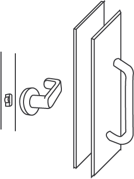
Figure 4.1.6.7 Examples of Accessible Hardware
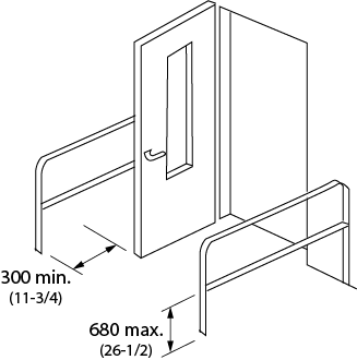
Figure 4.1.6.8 Detectable Safety Guards
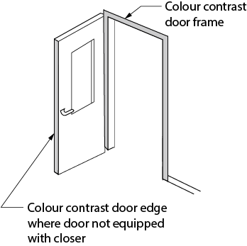
Figure 4.1.6.9 Colour Contrast at Doors
4.1.6 - Related Sections
4.1.1 Space and Reach Requirements
4.1.7 Gates, Turnstiles and Openings
4.1.8 Windows, Glazed Screens and Sidelights
4.4.2 Controls and Operating Mechanisms
4.4.7 Signage
4.4.10 Information Systems
4.4.11 Card Access, Safety and Security Systems
4.1.7 - Gates, Turnstiles and Openings
4.1.7 - Rationale
- Gates and turnstiles should address the full range of users that may pass through them. Single-bar gates designed to be at a convenient waist height for ambulatory persons are at neck and face height for children and chest height for persons who use wheelchairs or scooters.
- Revolving turnstiles are a physical impossibility for a person in a wheelchair to negotiate. They are also difficult for persons using canes or crutches, or persons with poor balance. An adjacent opening of an accessible width is essential for wheelchair access, as well as access for those using other mobility devices, strollers, walkers or delivery carts.
4.1.7 - Application
- Gates, turnstiles and openings shall comply with this section.
4.1.7 - Design Requirements
- Where gates or openings are provided through fences or screens to public use areas, such openings shall be accessible (i.e., a minimum of 950 mm (37-1/2 in.) wide), to allow free passage for persons who use a wheelchair or scooter. (Note: Hardware should be suitable for autonomous use, and any closing device should not be spring-loaded).
- Where turnstiles or other ticketing control devices are utilized which are not accessible, a gate or opening which is accessible shall be provided in the same location and shall incorporate the International Symbol of Access for Persons with Disabilities.
- Turnstiles shall incorporate a pronounced colour contrast to differentiate them from the surrounding environment.
- Where gates are incorporated into a chain-link fencing system, the poles at either side of the gate shall incorporate a pronounced colour contrast from the fence and the surrounding environment.
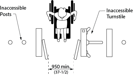
Figure 4.1.7.1 Access at Turnstile
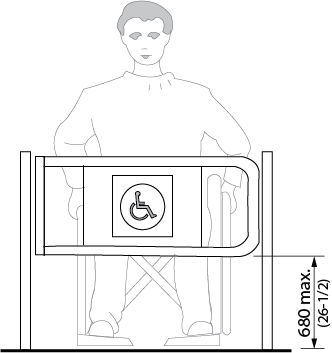
Figure 4.1.7.2 Access at Turnstile
4.1.7 - Related Sections
4.1.1 Space and Reach Requirements
4.1.4 Accessible Routes, Paths and Corridors
4.1.6 Doors
4.1.8 Windows, Glazed Screens and Sidelights
4.4.2 Controls and Operating Mechanisms
4.4.7 Signage
4.4.10 Information Systems
4.4.11 Card Access, Safety and Security Systems
4.1.8 - Windows, Glazed Screens and Sidelights
4.1.8 - Rationale
- Broad expanses of glazing in screens, sidelights and doors can be difficult to detect. While this may be a particular concern to persons with vision loss/no vision, it is possible for anyone to walk into a clear sheet of glazing especially if they are distracted or in a hurry.
- Persons who use wheelchairs or scooters experience the facility from a seated position thereby lowering their eye level and reach range. This necessitates the need for lower sill heights and easily reached operating mechanisms. Window controls and operating devices should also respect the limitations of hand strength or dexterity encountered with different types of disabilities, including arthritis.
4.1.8 - Application
- Windows, glazed screens, fully-glazed sidelights, fully-glazed doors and vision panels in doors shall comply with this section.
- Frameless glass doors and/or sidelights shall not be used.
4.1.8 - Design Requirements
- Fully-glazed doors and sidelights at exterior entrances or vestibules, as well as fully-glazed interior doors, screens and sidelights shall be marked with a continuous opaque strip that
- is colour and brightness contrasted to the background of the door;
- is at least 50 mm (2 in.) wide;
- is located across the width of the door at a height of 1350 to 1500 mm (53-1/8 to 59 in.) above the finished floor; and
- may incorporate a logo or symbol provided such logo or symbol does not diminish
- the opacity of the strip;
- the width of the strip;
- the colour and brightness contrast of the strip to the background of the door; and
- the continuity of the strip across the width of the door.
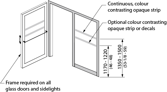
Figure 4.1.8.2 Fully Glazed Doors, Sidelights and Vision Panel Markings
- Optionally, a second row of decals, or a continuous strip, a minimum 50 mm (2 in.) wide and of highly contrasting colour to the background shall be provided, mounted with its centreline between 1170 mm (46 in.) and 1220 mm (48 in.) above the floor or ground.
- Where decals are used, they shall be located at a maximum of 150 mm (5-7/8 in.) from centre to centre. The decals can either be 50 mm (2 in.) square or round, and/or of a special design (e.g., a logo) provided the solid portion of the decals provides a high colour contrast and is easy to identify by persons with vision loss/no vision.
- Where etched or patterned glass is used, decals or stripes of a highly contrasting colour shall still be provided.
- Where frameless glass vision panels are used, exposed edges shall be identified with a vertical safety stripe, applied to cap the ends of each exposed glass panel.
- Where viewing windows or vision panels are provided,
- the sill height shall be no more than 760 mm (30 in.) from the floor; and
- where horizontal transoms are incorporated, the transoms shall not be located between 1060 mm (42 in.) and 1220 (48 in.) from the floor.
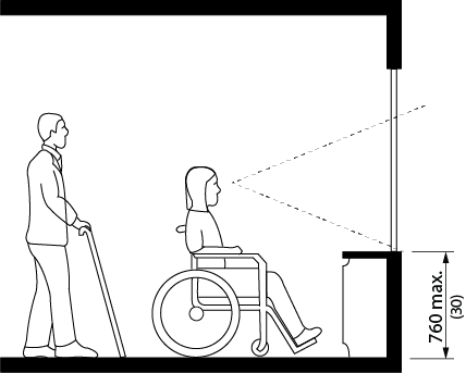
Figure 4.1.8.1 Window Sill Height
- In facilities with operable windows, window opening hardware shall
- be mounted between 400 mm (15-3/4 in.) and 1200 mm (47 in.) from the floor;
- be operable using one hand; and
- not require fine finger control, tight grasping, pinching, or twisting of the wrist to operate.
4.1.8 - Related Sections
4.1.1 Space and Reach Requirements
4.4.2 Controls and Operating Mechanisms
4.1.9 - Ramps
4.1.9 - Rationale
- Traditionally, ramps have been synonymous with wheelchair accessibility. However, ramps can be problematic in providing accessibility. Ramps can be difficult and dangerous to negotiate. Also, the physical space required for ramps makes them cumbersome to integrate into a facility. However, where a change in level already exists or cannot be avoided, a properly designed ramp can provide access for those using wheelchairs or scooters, pushing strollers or moving packages on a trolley.
- The design of the ramp is critical to its usefulness and safety. A steeply inclined ramp is difficult to ascend when using a wheelchair, and can increase the risk of the wheelchair tipping backwards. Descending a steep ramp can also be hazardous. Any cross slope will further increase the effort required to negotiate the ramp. Manoeuvring space at the top and bottom are also important factors in a ramps usability. Level areas at points along a long ramp enable an individual to rest.
- Textured surfaces, edge protection and handrails all provide important safety features. Heated surfaces are recommended to address the safety concerns associated with snow and ice.
4.1.9 - Application
- Any part of an accessible route with a slope steeper than 1:20 (5%) shall be considered a ramp and shall comply with this section.
4.1.9 - Design Requirements
- Accessible ramps shall be on an accessible route complying with 4.1.4.
- Where an accessible ramp is located in a barrier-free path of travel serving a building entrance, signage in compliance with 4.4.7 shall be installed to indicate the location of the accessible ramp and the accessible entrance.
- The running slope shall be between 1:20 (5%) and 1:15 (6.7%). In an interior retrofit situation where it is technically infeasible to provide a ramp with a running slope between 1:20 (5%) and 1:15 (6.7%), a running slope not steeper than 1:12 (8%) may be used for interior ramps. Exterior ramps cannot be steeper than 1:15 (6.7%). Shallower slopes are preferred.
- The maximum cross slope of ramp surfaces shall be 1:50 (2%).
- Ramps shall have level landings at the top and bottom of each run and also where the ramp changes direction.
- The maximum horizontal length between landings shall not exceed 9 m (29’-6”).
- Landings shall
- be at least as wide as the widest ramp run leading to it;
- have a minimum size not less than 2440 x 2440 mm (96 x 96 in.) if located at the top or bottom of a ramp or if served by a doorway. (In a retrofit situation where creating a suitably sized landing is technically infeasible, the required landing size may be reduced to 1670 x 1670 mm. (65-3/4 x 65-3/4 in.));
- where an intermediate landing at the switchback of a U-shaped ramp (Refer to Figure 4.1.9.1), have a length not less than 1670 mm (65-3/4 in.) and a width not less than 2440 mm (96 in.). (In a retrofit situation where creating a suitably sized landing is technically infeasible, the required landing width may be reduced to 2120 mm (84in));
- where there is a change of 90 degrees or more in the direction of the ramp, have a length not less than 1670 mm (65-3/4 in.) and a width no less than the width of the ramp; and
- where an intermediate landing at a straight ramp (Refer to Figure 4.1.9.1), have a length not less than 1670 mm (65-3/4 in.)
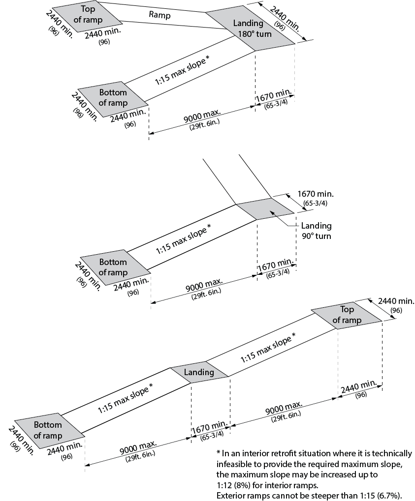
Figure 4.1.9.1 Minimum Ramp Landing Dimensions
- Ramp and landing surfaces shall be firm, stable, and slip-resistant.
- At slope transitions, ramps shall have a 40 - 60 mm (1-5/8 - 2-3/8 in.) wide colour-contrasted strip across the width of the ramp, located on the sloped surface.
- Outdoor ramps and their approaches shall be designed so that water will not accumulate on walking surfaces.
- Ramps and landings forming part of a ramp shall be protected by a wall or guard on both sides.
- Where a guard is provided, it shall
- comply with the requirements of the Ontario Building Code;
- have a minimum height of 1070 mm (42-1/8 in.) measured vertically from the ramp surface to the top of the guard;
- be designed so that no member located 140 - 900 mm (5-1/2 - 35-1/2 in.) above the ramp will facilitate climbing; and
- be provided
- with a curb at least 75 mm (3 in.) high on any side of the ramp where no solid enclosure or guard is provided; and
- with railings or other barriers that extend to within 50 mm (2 in.) of the finished ramp, or have a curb not less than 75 mm (3 in.) high.
- Ramps shall be equipped with handrails which:
- are on both sides;
- comply with 4.1.12;
- are continuous on the inside of switchback (U-shaped) or L-shaped ramps;
- extend horizontally at least 300 mm (11-3/4 in.) beyond the top and bottom of the ramp and return to the wall, floor, or post;
- measure between 865 mm (34 in.) and 920 mm (36 in.) from the ramp surface to the top of the handrail, except handrails not meeting these requirements are permitted if installed in addition of the required handrail;
- have a width between at least one set of handrails of 950 mm - 1200 mm (37-1/2 to 48 in.); and
- terminate to a wall, floor, post or other manner that will not obstruct pedestrian travel or create a hazard.
- Where ramps are greater than 2200 mm (86-5/8 in.) wide, one or more intermediate handrails which are continuous between landings must be provided and located so that there is 900 mm (35-1/2 in.) between at least one set of handrails.
- Exception: Where a ramp serves as an aisleway for fixed seating, the requirement for ramp handrails does not apply.
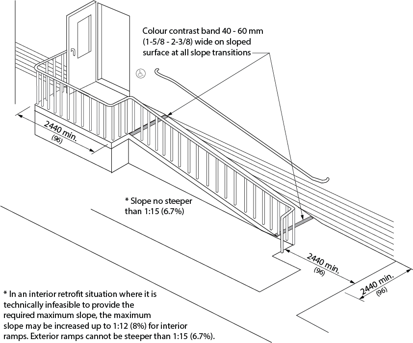
Figure 4.1.9.2 Ramp Criteria
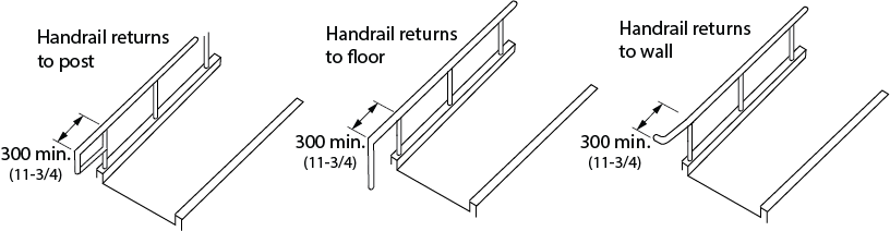
Figure 4.1.9.3 Horizontal Handrail Extensions
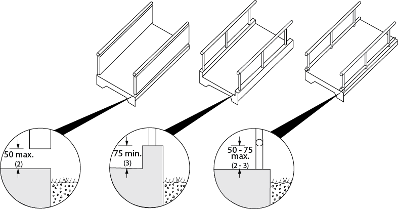
Figure 4.1.9.4 Edge Protection at Ramps
- Designated areas for snow piling to be provided at exterior ramps, located away from pedestrian routes.
4.1.9 - Related Sections
4.1.1 Space and Reach Requirements
4.1.2 Ground and Floor Surfaces
4.1.6 Doors
4.1.10 Curb Ramps
4.1.12 Handrails
4.4.7 Signage
4.4.8 Detectable Warning Surfaces
4.4.12 Glare and Light Sources
4.4.13 Lighting
4.4.14 Materials and Finishes
4.4.15 Texture and Colour
4.1.10 - Curb Ramps
4.1.10 - Rationale
- In the interest of moving people safely and efficiently off a roadway, the design of curb ramps is very important. The same issues related to the slopes of ramps apply equally to slopes of curb ramps. A well-designed curb ramp can be spoiled by an uneven or gapped transition between the road surface and curb ramp. Flared sides on the curb ramp eliminate the hazard of pedestrians stepping off of an edge. While a smooth transition and minimal slope are ideal for someone in a wheelchair, they are a potential hazard to an individual with vision loss/no vision who may not notice the transition from sidewalk to street. Textured surfaces become an important safety feature in this scenario.
- Snow accumulation at curb ramps should be removed completely after each snow fall.
4.1.10 - Application
- Curb ramps complying with this section shall be provided wherever any path of travel crosses a curb.
4.1.10 - Design Requirements
- Accessible curb ramps shall be on an accessible route complying with 4.1.4.
- Accessible curb ramps shall align with the safe pedestrian crossing route across the vehicle roadway.
- The running slope shall be between 1:50 and 1:20 (2%-5%). In a retrofit situation where it is technically infeasible to achieve these slopes, a running slope no steeper than 1:12 (8%) may be used. The maximum cross slope shall be no more than 1:50 (2%).
- The minimum width of curb ramps, exclusive of flared sides, shall be 1500 mm (59 in.), except where the Depressed Curb configuration is used (Refer to Figure 4.1.10.2), where the minimum width at the top of the ramp may be reduced to 1220 mm (48 in.).
- Flared sides shall typically be 900 mm (35-1/2 in.) as illustrated, measured at the curb location, with a slope not more than 1:12 (8.3%) where pedestrians are likely to walk across them.
- Curb ramp configuration shall conformn to all Town and Region standards. The following diagrams are representative of these Municipal and Regional standards.
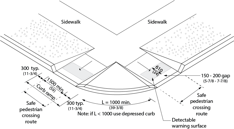
Figure 4.1.10.1 Standard Curb Ramp
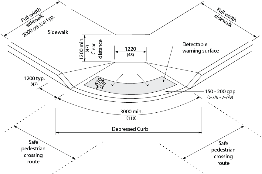
Figure 4.1.10.2 Alternate Curb Ramp
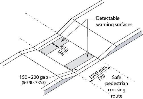
Figure 4.1.10.3 Curb Ramp at Narrow Median Sidewalk Crossing
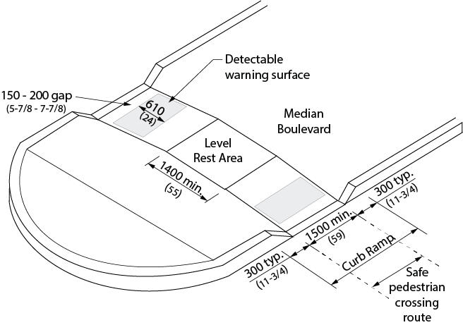
Figure 4.1.10.4 Curb Ramp at Wide Median Sidewalk Crossing
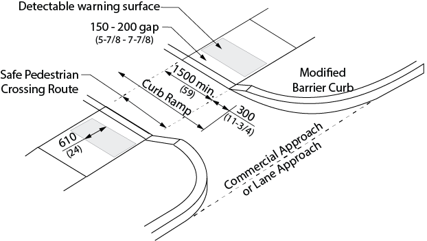
Figure 4.1.10.5 Curb Ramp at Commercial or Lane Approach (Refer also to Ontario Provincial Standards for Roads & Public Works)
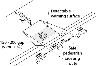
Figure 4.1.10.6 Curb Ramp at Mid-Block Crossing (Refer also to Ontario Provincial Standards for Roads & Public Works)
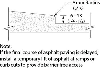
Figure 4.1.10.7 Curb Ramp Transition at Pavement
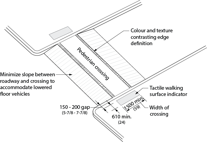
Figure 4.1.10.8 Raised Pedestrian Crossing (Refer also to Ontario Provincial Standards for Roads & Public Works)
- The maximum cross fall of gutters and road surfaces immediately adjacent to curb ramps shall be 1:20 (5%).
- Curb ramps at pedestrian crosswalks shall be wholly contained within the area designated for pedestrian use.
- Surfaces of curb ramps shall
- be slip-resistant; and
- incorporate a truncated dome detectable warning surface
- in compliance with 4.4.8;
- be located at the bottom portion of the curb ramp;
- 610 mm (24 in.) in depth, starting 150-200 (5-7/8 to 7-7/8 in) back from the edge of the curb;
- extending the entire width of the ramp; and
- have a smooth transition from the ramp and adjacent surfaces.
- Designated areas for snow piling to be provided at all curb ramps, located away from pedestrian routes.
Depressed Curbs:
- Where a depressed curb is provided on an exterior path of travel, the depressed curb shall
- have a maximum running slope of 1:20 (5%);
- be aligned with the direction of travel; and
- where provided at a pedestrian crossing, it shall incorporate a flat-topped domes or cones detectable warning surface that
- complies with section 4.4.8;
- is located at the bottom portion of the depressed curb that is flush with the roadway;
- is set back 150 - 200 mm (5-7/8 - 7-7/8 in.) from the curb edge; and
- is a minimum of 610 mm (24 in.) in depth.
4.1.10 - Related Sections
4.1.1 Space and Reach Requirements
4.1.2 Ground and Floor Surfaces
4.4.8 Detectable Warning Surfaces
4.4.12 Glare and Light Sources
4.4.14 Materials and Finishes
4.4.15 Texture and Colour
4.1.11 - Stairs
4.1.11 - Rationale
- Stairs that are comfortable for many adults may be challenging for children, seniors or persons of short stature. Poorly designed nosings can present tripping hazards, particularly to persons with prosthetic devices or those using canes. Cues to warn a person with vision loss/no vision of an upcoming set of stairs are vitally important.
- The appropriate application of handrails will aid all users navigating stairways.
4.1.11 - Application
- Interior and exterior stairs shall comply with this section. In a retrofit situation
- stairs need not comply if they connect levels that are accessible by an elevator, ramp or other accessible means of vertical access; and
- dimensional changes to steps and landings are not required however all other design requirements must be met.
4.1.11 - Design Requirements
- A flight of stairs shall
- have uniform riser heights (rise) and uniform tread depths (run);
- have a rise not more than 180 mm (7 in.) and not less than 125 mm (4-7/8 in.) high;
- have a run not more than 355 mm (14 in.) and not less than 280 mm (11 in.) deep, measured from riser to riser;
- incorporate detectable warning surfaces in compliance with 4.4.8.;
- have tread surfaces that are slip-resistant; and
- have no open risers.
- Nosings shall
- project not more than 25 mm (1 in.);
- have no abrupt undersides;
- have a curved or bevelled leading tread edge of between 6 mm (1/4 in.) and 10 mm (3/8 in.);
- where projecting, be sloped to the riser at an angle not less than 60 degrees to the horizontal;
- be illuminated to a level of at least 100 lux (9.2 ft-candles);
- have a slip-resistant finish; and
- have the horizontal surface of the stair nosing in colour contrast with the remainder of the tread.
- Stairs shall incorporate detectable warning surfaces in compliance with with 4.4.8.
- Handrails for stairs shall
- comply with 4.1.12;
- be installed on both sides;
- be of uniform height, ranging between 865 mm (34 in.) and 920 mm (36 in.) above the stair nosing;
- have a continuous inside handrail on switchback stairs;
- extend at the bottom of the stairs for a distance of one tread depth beyond the first riser, then horizontally not less than 300 mm (11-3/4 in.), at a height ranging between 865 mm (34 in.) and 920 mm (36 in.) above the floor;
- extend horizontally at the top of the stairs not less than 300 mm (11-3/4 in.), at a height ranging between 865 mm (34 in.) and 920 mm (36 in.) above the floor; and
- return to the wall, or post in a manner that will not obstruct pedestrian travel or create a hazard.
- Stairs and landings forming part of a stair shall be protected by a wall or guard on both sides.
- Where a guard is provided, it shall
- comply with the requirements of the Ontario Building Code;
- have a minimum height of 900 mm (35-1/2 in.) measured vertically to the top of the guard from a line drawn through the outside edge of stair nosings; and
- have a minimum height of 1070 mm (42-1/8 in.) around landings.
- Where stairs are greater than 2200 mm (86-5/8 in.) wide, one or more intermediate handrails which are continuous between landings must be provided and located so that they are no more than 1650 mm (65 in.) apart and there is 900 mm (35-1/2 in.) between at least one set of handrails.
- Designated areas for snow piling to be provided at exterior stairs, located away from pedestrian routes.
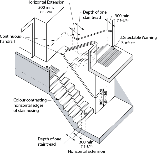
Figure 4.1.11.1 Stair Design Criteria
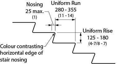
Figure 4.1.11.2 Stair Tread Criteria
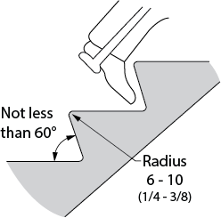
Figure 4.1.11.3 Raked Riser
4.1.11 - Related Sections
4.1.1 Space and Reach Requirements
4.1.2 Ground and Floor Surfaces
4.1.6 Doors
4.1.12 Handrails
4.4.7 Signage
4.4.8 Detectable Warning Surfaces
4.4.12 Glare and Light Sources
4.4.13 Lighting
4.4.14 Materials and Finishes
4.4.15 Texture and Colour
4.1.12 - Handrails
4.1.12 - Rationale
- In the design of handrails, consideration must be given to the range of hands that will grasp them. A handrail profile should be graspable for an adult hand as well as a child or a person with arthritis. The same is true for the heights of handrails.
- Extensions of the handrails at the top and bottom of stairs, along with the use of a contrasting colour, provide important cues for a person with vision loss/no vision, and provide a support to ensure a safe and stable gait before ascending or descending the stairs. A continuous handrail with no interruptions ensures that a handhold will not be broken.
- The clear space between the wall and handrail is also essential, as it must provide a clear area for the hand and knuckles but must not offer enough space into which an arm may slip during a fall or stumble on the stairs.
4.1.12 - Application
- Handrails shall comply with this section.
4.1.12 - Design Requirements
- Handrails shall
- be mounted 865 - 920 mm (34-36 in.) high, measured vertically from a line drawn through the outer edges of the stair nosings or from the surface of a ramp, except handrails not meeting these requirements are permitted if installed in addition to the required handrail;
- have a circular section 30-40 mm (1-3/16 in. – 1-9/16 in.) in diameter or any non-circular shape, with a graspable portion that has a perimeter not less than 100 mm (4 in.) and not more than 125 mm (5 in.) whose largest cross-sectional dimension is not more than 45 mm (1-3/4 in.);
- be free of any sharp or abrasive elements;
- have continuous gripping surfaces, without interruption by newel posts, other construction elements, or obstructions that can break a handhold;
- have a clear space between the handrail and the wall or guard of
- at least 50 mm (2 in.); or
- at least 60 mm (2-3/8 in.) where the wall has a rough surface;
- extend parallel to the floor or ground surface a minimum distance of 300 mm (11-3/4 in.) beyond the beginning or end of a stair or ramp section; and
- terminate to a wall, floor, post or other manner that will not obstruct pedestrian travel or create a hazard.
- A recess containing a handrail shall extend at least 450 mm (17-3/4 in.) above the top of the rail.
- Handrails and their supports shall be designed and constructed to withstand the loading values obtained from the non-concurring application of
- a concentrated load of not less than 0.9 kN (200 lb.) applied at any point and in any direction; and
- a uniform load of not less than 0.7 kN/m (47 lb./ft.) applied in any direction to the handrail.
- Handrails shall incorporate a pronounced colour contrast, to differentiate them from the surrounding environment.
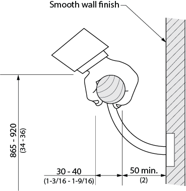
Figure 4.1.12.1 Handrail
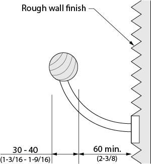
Figure 4.1.12.2 Handrail at Rough Wall
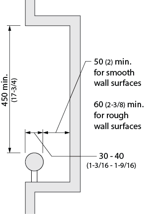
Figure 4.1.12.3 Handrail in Recess
4.1.12 - Related Sections
4.1.1 Space and Reach Requirements
4.1.9 Ramps
4.1.11 Stairs
4.4.15 Texture and Colour
4.1.13 - Elevators
4.1.13 - Rationale
- The buttons used on elevators need to address a range of functional issues, including reach, dexterity and vision loss/no vision, as discussed in 4.4.2 and 4.4.15. More specific to elevators is the need to provide audible cues for individuals with vision loss/no vision to identify different floor levels, as well as the direction of travel. These are, in fact, of benefit to anyone who uses the elevator. Adequate door-closing delays provide individuals using mobility devices additional time to reach, enter or exit the elevator car. The installation of a mirror can assist individuals using mobility devices to back out of an elevator where there is not sufficient space to turn around.
4.1.13 - Application
- One passenger elevator complying with this section shall serve each level, including mezzanines, in all multi-storey facilities, unless exempted below. If more than one elevator is provided, each passenger elevator shall comply with this section.
- Freight elevators shall not be required to meet the requirements of this section, unless the only elevators provided are used as combination passenger and freight elevators for use by the public and employees.
- Elevator access is not required:
- in elevator pits, elevator penthouses, mechanical rooms, piping or equipment catwalks;
- when accessible ramps in compliance with 4.1.9 are used in lieu of an elevator;
- to levels of fire halls and ambulance stations not served by grade-level entry, which do not contain public use facilities; and
- when platform lifts (wheelchair lifts) in compliance with 4.1.14 and applicable Provincial Codes are used in lieu of an elevator, only under the following conditions:
- to provide an accessible route to a performing area in an assembly occupancy;
- to comply with wheelchair viewing position line-of-sight and dispersion requirements of 4.3.2;
- to provide access to incidental occupied spaces and rooms that are not open to the general public and which house no more than five persons, including, but not limited to, equipment control rooms and projection booths; and
- to provide access to raised judges’ benches, clerks’ stations, speakers’ platforms, jury boxes and witness stands or to depressed areas, such as the well of a court.
4.1.13 - Design Requirements
- Accessible elevators shall be on an accessible route in compliance with 4.1.4.
- Accessible elevators shall be identified by signage in compliance with applicable provisions of 4.4.7.
- Elevators shall be automatic and be provided with a two-way automatic-levelling device to maintain the floor level to ± 13 mm (1/2 in.).
- Power-operated horizontally sliding car and landing doors opened and closed by automatic means shall be provided.
- The clear width for elevator doors shall be minimum 950 mm (37-1/2 in.). In a retrofit situation where it is technically infeasible to provide a clear width of 950 mm (37-1/2 in.), the clear elevator door width may be reduced to 900 mm (35-1/2 in.). In high-use public facilities, the door clear opening width should be not less than 1065 mm (42 in.).
- Doors shall be provided with a door re-opening device that will function to stop and reopen the car door and an adjacent hoist way door to minimum 950 mm (37-1/2 in.), in the event the car door is obstructed while closing. This re-opening device shall also be capable of sensing an object or person in the path of a closing door at a nominal 125 ± 25 mm (5 ± 1 in.) and 735 ± 25 mm (29 ± 1 in.) above the floor without requiring contact for activation.
- Elevator doors should remain fully open for minimum 8 seconds. This time may be reduced by operation of the door-close button.
- The minimum distance between the walls or between wall and door, excluding return panels, shall not be less than 1725 x 1525 mm (68 in. x 60 in.). In facilities with high public use, such as arenas, libraries or entertainment complexes, the distance between walls or between wall and door shall be 2030 x 1525 mm (80 in. x 60 in.).
- Exception: In a retrofit situation where it is technically infeasible to install an appropriately sized elevator, a LU/LA (Limited Use/Limited Application) elevating device with a platform length of at least 1525 mm (60 in.), may be used. For Town of Aurora facilities, on a go forward basis, LU/LA's shall not be installed in new buildings or major renovations. Instead, an elevator is recommended.
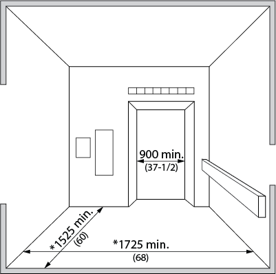
Figure 4.1.13.1 Elevator Cab
* In high-use public facilities, increase minimum dimensions to 2030 x 1525 mm (80 x 60 in.) with a clear door opening width of at least 1065 mm (42 in.)
- Car controls shall be readily accessible from a wheelchair upon entering an elevator.
- Floor register buttons in elevator cabs shall
- be a minimum 19 mm (3/4 in.) in size and may be raised, flush or recessed. The depth of flush or recessed buttons when they are being operated shall not exceed 10 mm (3/8 in.); and
- be provided with visual and momentary audible indicators to show when each call is registered. The visual indicators shall be extinguished when each call is answered.
- All car control buttons shall be designated by Grade 2 Braille characters and by raised standard alphabet characters for letters, Arabic characters for numbers, and standard symbols. Markings shall be a minimum of 16 mm (5/8 in.) high and raised a minimum of 0.75 mm (1/32 in.), placed immediately to the left of the buttons to which they apply.
- Exception: Where the call buttons are mechanical, the raised markings may be on the buttons.
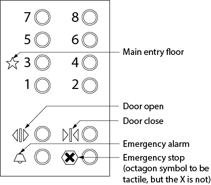
Figure 4.1.13.4 Tactile Symbols
- Emergency car controls and door-operating buttons shall be grouped together at the bottom of the control panel. The centre line of the alarm button and the emergency stop switch shall be not less than 890 mm (35 in.) above the floor. The centre line of the highest floor button shall be no higher than 1200 mm (47 in.) above the floor. Other controls may be located where it is convenient.
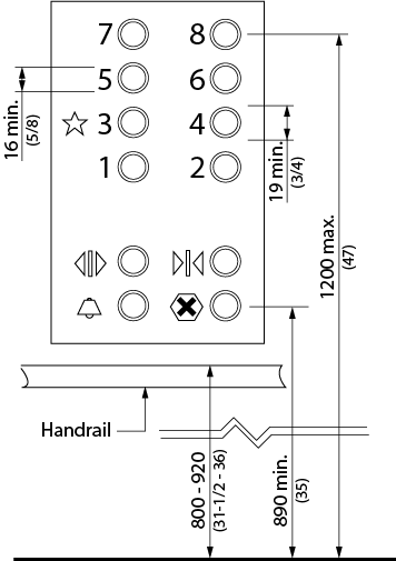
Figure 4.1.13.2 Control Panel
- An indicator shall be provided in the car to show the position of the car in the hoist way, by illuminating the indicator corresponding to the landing at which the car is stopped or passing. Indication characters shall be on a contrasting colour background and a minimum of 16 mm (5/8 in.) high.
- Floors of elevator cabs shall have a firm and slip-resistant surface that permits easy movement of wheelchairs or scooters.
- Handrails shall be provided on all non-access walls at a height of 800 to 920 mm (31-1/2 to 36 in.) with a space of 40 to 45 mm (1-9/16 to 1-3/4 in.) between the rails and wall.
- The illumination at the car controls and landing sill shall be not less than 100 lux (10 ft-candles).
- The centre line of hall call buttons shall be 920 ± 25 mm (36 ± 1 in.) above the floor. Buttons shall be a minimum of 20 mm (13/16 in.) in size, mounted one above the other.
- Hall visual indication shall be provided to show each call that is registered and that is extinguished when the call is answered.
- Hall or in-car lanterns shall be provided. The centre line of the fixture shall be a minimum of 1830 mm (72 in.) above the floor. An audible signal shall be provided when the elevator stops at the landing. Visual elements shall be a minimum of 60 mm (2-3/8 in.) in the smallest direction.
- All elevator hoist way entrances shall have raised Arabic numerals and Braille floor designations provided on both jambs. The characters shall be a minimum of 50 mm high (2 in.) and raised at least 0.75 mm (1/32 in.) and shall be placed on both sides of the door jambs, with the centreline at 1500 ± 25 mm (59 ± 1 in.) from the floor.
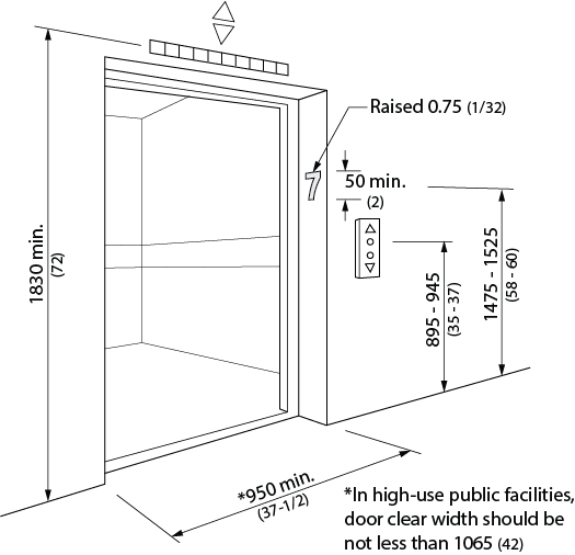
Figure 4.1.13.3 Elevator Entry
- As the car stops at a floor, the floor and direction of travel shall be announced using voice-annunciation technology.
- Elevators shall be linked by an emergency call system to a monitored location within the facility with two-way communication ability. The highest operable portion of the 2-way communication system shall be a maximum of 1200 mm (47 in.) above the floor of the car. It shall be identified by a raised symbol and lettering located adjacent to the device. The symbol shall be a minimum of 38 mm (1-1/2 in.) high and raised a minimum of 0.75 mm (1/32 in.). Permanently attached plates are acceptable. If the system uses a handset, then the length of the cord from the panel to the handset shall be minimum 735 mm (29 in.). Additionally, the handset shall be equipped with a receiver that generates a magnetic field in the area of the receiver cap, and the handset shall have a volume control and shall comply with CSA Standard T515. If the system is located in a closed compartment, the compartment door and hardware shall conform to 4.4.2. The emergency intercommunication system shall not require voice communication.
- Lighting in elevator cabs shall be minimum 100 lux (9.2 ft-candles), measured at the floor level and at the same lighting level as the adjacent lobby space.
- Mirrors shall not be used below a height of 2000 mm (78-3/4 in.) within elevator cabs as a finish material on the wall opposite the door.
- Where the dimension of elevator cabs is less than 1500 mm (59 in.) in any direction, an angled mirror shall be provided above a height of 2000 mm (78-3/4 in.) on the wall opposite the door, to assist persons who use wheelchairs to back out.
- Floor finishes within elevator cabs shall comply with 4.1.2.
- Where an elevator serves only two floors, it shall be programmed to move automatically, without the need to activate in-car control buttons.
- Elevator doors shall incorporate pronounced colour contrast, to differentiate them from the surrounding environment.
- There shall be a pronounced colour contrast between the car sill and the facility floor.
4.1.13 - Related Sections
4.1.1 Space and Reach Requirements
4.1.2 Ground and Floor Surfaces
4.1.6 Doors
4.1.12 Handrails
4.1.14 Platform Lifts
4.4.2 Controls and Operating Mechanisms
4.4.7 Signage
4.4.9 Public Address Systems
4.4.11 Card Access, Safety and Security Systems
4.4.12 Glare and Light Sources
4.4.13 Lighting
4.4.14 Materials and Finishes
4.4.15 Texture and Colour
4.1.14 - Platform Lifts
4.1.14 - Rationale
- Platform lifts are typical in retrofit applications. Elevators that are used by all facility users are preferred to platform lifts which tend to segregate persons with disabilities and limit space at entrance and stair locations. Furthermore, independent access is often compromised, as platform lifts are often controlled by key operation. Whenever possible, grading or integrated elevator access should be incorporated to avoid the use of lifts.
- If there are no suitable alternatives, lifts must be selected to permit the spatial requirement of larger mobility devices such as scooters.
4.1.14 - Application
- Accessible platform lifts shall comply with this section.
- Platform lifts may only be used in lieu of an elevator or ramp where allowable under 4.1.13.
- Exception: Where it is technically infeasible to install an elevator, LU/LA (Limited Use/Limited Application) elevating device, or other accessible means of change of level.
4.1.14 - Design Requirements
- Accessible platform lifts shall
- The platform size shall be no less than 890 x 1525 mm (35 x 60 in.).
- The platform shall incorporate safety wheel-guards along all exposed edges.
- The doors to the platform lift shall comply with 4.1.6.
- Controls and operating mechanisms shall comply with 4.4.2.
- Platform lifts shall be linked by an emergency call system to a monitored location within the facility, with two-way communication ability. The highest operable portion of the two-way communication system shall be a maximum of 1200 mm (47 in.) from the floor of the platform. If the system uses a handset, then the length of the cord from the panel to the handset shall be at least 735 mm (29 in.). If the system is located in a closed compartment, the compartment door and hardware shall conform to 4.4.2.
- Floor finishes within platform lifts shall comply with 4.1.2 and 4.4.14.
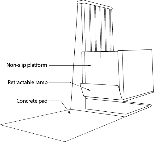
Figure 4.1.14.1 Vertical Platform Lift
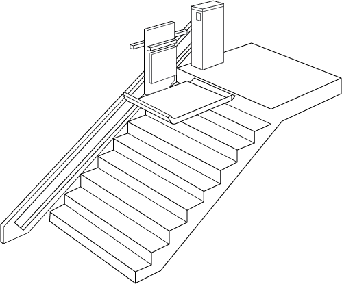
Figure 4.1.14.2 Inclined Platform Stair-Lift
4.1.14 - Related Sections
4.1.1 Space and Reach Requirements
4.1.2 Ground and Floor Surfaces
4.1.6 Doors
4.1.12 Handrails
4.1.13 Elevators
4.4.2 Controls and Operating Mechanisms
4.4.7 Signage
4.4.9 Public Address Systems
4.4.11 Card Access, Safety and Security Systems
4.4.12 Glare and Light Sources
4.4.13 Lighting
4.4.14 Materials and Finishes
4.4.15 Texture and Colour
4.2 - Washroom Facilities
4.2.1 - Toilet Facilities
4.2.1 - Rationale
- As an integral feature of a facility, washroom facilities should accommodate the range of people that will use the space. Although many persons with disabilities use toilet facilities independently, some may require assistance. Where the individual providing assistance is of the opposite gender then typical gender-specific washrooms are awkward and an individual washroom is preferred.
- Parents and caregivers with small children and strollers may also benefit from a large, individual washroom with toilet and change facilities contained within the same space.
- Circumstances such as wet surfaces and the act of transferring between toilet and wheelchair or scooter can make toilet facilities accident-prone areas. An individual falling in a washroom with a door that swings inward could prevent his or her own rescuers from opening the door. Due to the risk of accidents, design decisions such as door swings and material finishes have safety implications and therefore make toilet facilities a prime location for emergency call switches. The appropriate design of all features will increase the usability and safety of all toilet facilities.
- The identification of washrooms involves design issues that must be considered. For children or someone who cannot read text, a symbol or pictogram is preferred. A person with vision loss/no vision would also benefit from accessible signage. Features such as colour-contrasting door frames and door hardware will also increase accessibility.
4.2.1 - Application
- Where toilet facilities are provided, each public or common use toilet facility shall comply with this section. Other toilet rooms provided for the use of occupants of specific spaces (i.e. a private toilet room for the occupant of a private office) shall be adaptable.
- In a retrofit situation where it is technically infeasible to make existing public or common use toilet facilities accessible, the installation of at least one universal washroom per floor and in compliance with 4.2.7, located in the same area as existing toilet facilities, will be permitted in lieu of modifying existing toilet facilities to be accessible.
- In addition to any accessible public or common use toilets, at least one universal washroom in compliance with 4.2.7 shall be provided in all public buildings and on every floor level in assembly areas where the floor incorporates common or public use washroom facilities containing four or more toilet and/or urinal fixtures.
- The minimum number of universal washrooms per building shall be as shown on Table 4.2.1.
| Number of storeys in Building | Minimum number of Universal Washrooms per Building |
|---|---|
| 1 to 3 | 1 |
| 4 to 6 | 2 |
| Over 6 | 3 plus 1 for each additional increment of 3 storeys in excess of 6 storeys. |
- The minimum number of accessible toilet stalls within washrooms shall comply with 4.2.2.
- If individual washrooms are not visible from the common or public use washrooms, directional signage in compliance with 4.4.7 shall be provided.
- For public buildings, washrooms that open onto after hours public outdoor or indoor space is beneficial.
- Where bathing facilities are provided on a site, in conjunction with or in addition to toilet facilities, each such public or common use bathing facility shall comply with this section in addition to 4.2.8, and other applicable sections of this standard.
- For single-user portable toilet units clustered at a single location, a minimum of 5% but no less than one toilet unit in compliance with this section shall be provided at clusters wherever typical inaccessible units are provided. (Exception: Portable toilet units at construction sites used exclusively by construction personnel are not required to comply with this section.)
- Where a universal washroom is provided primarily for the use of persons of both genders with physical disabilities, in lieu of facilities for persons with physical disabilities in washrooms used by the general public, the individual washroom shall be provided on the same floor level within 45 m (147 ft. 8 in.) of the washrooms used by the general public.
4.2.1 - Design Requirements
- Accessible toilet facilities shall
- All entrance doors to accessible toilet rooms shall
- comply with 4.1.6;
- not swing into the clear floor space required for any fixture;
- have a minimum 1700 mm (67 in.) clearance between the inside face of an in-swinging entrance door and the outside face of an adjacent toilet stall.
- Accessible fixtures and controls within toilet and bathing rooms shall be on an accessible route complying with 4.1.4; and
- have a clear floor space in front of the stall or enclosure of at least 1500 mm (59 in.) between the outside face of the accessible stall and any wall-mounted fixture or obstruction, with a preferred clearance of 1525 mm (60 in.).
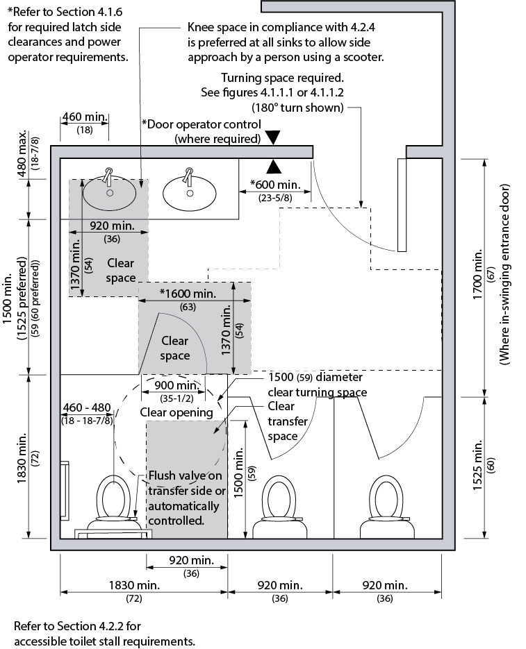
Figure 4.2.1.1 Washroom Dimensions
4.2.1 - Related Sections
4.1.1 Space and Reach Requirements
4.1.2 Ground and Floor Surfaces
4.1.3 Protruding and Overhead Objects
4.1.6 Doors
4.2.2 Toilet Stalls
4.2.3 Toilets
4.2.4 Lavatories
4.2.5 Urinals
4.2.6 Washroom Accessories
4.2.7 Universal Washrooms
4.2.8 Showers
4.2.9 Grab Bars
4.4.2 Controls and Operating Mechanisms
4.4.7 Signage
4.4.12 Glare and Light Sources
4.4.13 Lighting
4.4.14 Materials and Finishes
4.4.15 Texture and Colour
4.2.2 - Toilet Stalls
4.2.2 - Rationale
- Door swings are normally outward for safety reasons and space considerations, but this makes it difficult to close the door once inside. A handle mounted part way along the door makes it easier for someone to close the door behind them.
- Minimum requirements for non-accessible toilet stalls are included to ensure that persons who do not use wheelchairs or scooters can be adequately accommodated within any toilet stall. Universal features include accessible hardware and a minimum stall width to accommodate persons of large stature or parents with small children.
4.2.2 - Application
- Accessible toilet stalls shall comply with this section.
- Where toilet stalls are provided in a toilet or bathing facility, then the number of accessible toilet stalls designated to accommodate persons with disabilities shall comply with Table 4.2.2.
- All other toilet stalls within a facility (i.e., those considered to be non-accessible) shall be minimum 920 mm (36 in.) wide by 1525 mm (60 in.) long, and shall incorporate door-locking mechanisms in compliance with this section.
- At least one toilet stall within each non-accessible washroom shall be designated as an ambulatory toilet stall and shall comply with the ambulatory stall requirements of this section.
| # of toilet stalls within the washroom | Required # of accessible toilet stalls |
|---|---|
| 1 - 5 | 1 |
| 5 - 16 | 2 |
| 17 - 20 | 3 |
| 21 - 30 | 4 |
| Over 30 | 5 plus 1 for each additional increment of 10. |
4.2.2 - Design Requirements
- Accessible toilet stalls shall
- be on an accessible route in compliance with 4.1.4.
- have a clear floor space in front of the stall or enclosure of at least 1500 mm (59 in.) between the outside face of the accessible stall and any wall-mounted fixture or obstruction, with a preferred clearance of 1525 mm (60 in.).
- have internal dimensions at least 1830 x 1830 mm (72 x 72 in.);
- have a clear turning space within the stall of at least 1500 mm (59 in.) in diameter;
- have a toilet fixture in compliance with 4.2.3;
- be equipped with a collapsible coat hook mounted not more than 1200 mm (47 in.) above the floor on a side wall and projecting not more than 50 mm (2 in.) from the wall; and
- have a minimum 920 mm (36 in.) x 1500 mm (59 in.) clear transfer space on one side of the toilet fixture.
- Where more than one accessible toilet stall is provided within a toilet or bathing facility, the stalls shall be configured with the clear transfer space (i.e., the open space beside the toilet) on opposite sides of the toilet fixtures.
- Every toilet stall door shall
- be capable of being locked from the inside;
- incorporate hardware that is capable of being released from the outside in case of an emergency;
- incorporate door hardware that:
- is operable with one hand, using a closed fist;
- does not require fine finger control, tight grasping, pinching, or twisting of the wrist;
- requires a force of not more than 22 N (4.9 lb.) to activate (e.g., sliding bolt or lever); and
- mounted between 900 mm (35-1/2 in.) and 1100 mm (43-1/4 in.) above the floor.
- Accessible toilet stall doors shall
- provide a clear opening of at least 900 mm (35-1/2 in.) with the door in the open position. In a retrofit situation where it's technically infeasible to provide the required clear opening, the clear opening may be reduced to 860 mm (33-3/4 in.);
- swing outward, unless additional clear floor space of at least 920 mm x 1500 mm (36 in. x 59 in.) is provided within the stall and does not interfere with the arc of the door swing;
- be aligned with the clear transfer space adjacent to the toilet fixture;
- be equipped with gravity hinges so that the door closes automatically;
- be provided with a “D”-type contrasting-coloured door pull, at least 140 mm (5-1/2 in.) long, on the inside of an out-swinging door, located so that the centre line is between 200 and 300 mm (7-7/8 in. and 11-3/4 in.) from the hinged side of the door mounted between 750 - 850 mm (29-1/2 - 33 in.); and
- be provided with a “D”-type contrasting-coloured door pull at least 140 mm (5-1/2 in.) long, on both sides of the door, located near the latch, mounted between 750 - 850 mm (29-1/2 - 33 in.);
- Designated ambulatory toilet stalls shall
- be at least 1500 mm (59 in.) deep and 920 - 940 mm (36 - 37 in.) wide;
- have the toilet fixture centred between the partition walls;
- have a door that provides a clear opening width of at least 810 mm (32 in.), which swings out unless the minimum stall dimensions are not located within the door swing;
- be equipped with gravity hinges;
- have latch-side pulls in compliance with this section; and
- be equipped with L-shaped grab bars on both sides of the toilet in compliance with 4.2.3 and 4.2.9.
- Toilet stall partitions and doors shall be colour-contrasted with the surrounding environment.
- Where an airport style (door-free) washroom entry is used, the set back wall shall be painted a contrasting colour for easier depth perception and entry wayfinding.
- Toilets, flush controls and other elements shall be designed to meet the requirements of 4.2.3.
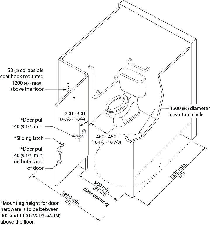
Figure 4.2.2.1 Accessible Toilet Stall
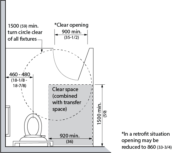
Figure 4.2.2.2 Accessible Toilet Stall with In-Swinging Door
4.2.2 - Related Sections
4.1.1 Space and Reach Requirements
4.1.3 Protruding and Overhead Objects
4.1.6 Doors
4.2.3 Toilets
4.2.6 Washroom Accessories
4.2.9 Grab Bars
4.4.2 Controls and Operating Mechanisms
4.4.13 Lighting
4.4.15 Texture and Colour
4.2.3 - Toilets
4.2.3 - Rationale
- Automatic flush controls are preferred. If flushing mechanisms are not automated, then consideration must be given to the ability to reach a switch and the hand strength or dexterity required to operate it. Lever style handles on the transfer side of the toilet facilitate these considerations.
- Appropriate placement of grab bars makes sitting and standing or transfers between the toilet and a mobility device safer.
4.2.3 - Application
- Accessible toilets shall comply with this section. Wall-mounted toilets are preferred except where weight requirements dictate otherwise.
4.2.3 - Design Requirements
- Toilet fixtures shall have
- the top of the seat 460 mm (18 in.) above the floor;
- no spring-activated seat;
- a back support where there is no seat lid or tank; and
- the tank top securely attached.
- Toilets shall be located between 460 and 480 mm (18 to 18-7/8 in.) away from the adjacent wall measured from the centre line of the toilet to the surface of the wall.
- A clear transfer space, minimum 920 mm (36 in.) wide and 1500 mm (59 in.) deep from the edge of the water closet designed to permit a wheelchair or scooter to back into a clear space beside a toilet fixture, shall be provided on one or both sides of the toilet fixture in all accessible toilet stalls (see 4.2.2.) and in universal washrooms (see 4.2.7.).
- The clear transfer space shall be clear of obstructions (such as garbage bins or baby change tables). Exception: Sanitary napkin disposal units may be installed within the transfer space provided they are recessed or protrude not more than 100 mm (4 in.) into this space.
- Toilet flush controls shall be
- hand operated by use of a closed fist with a force of not more than 22N;
- located between 500 - 900 mm (19-5/8 - 35-1/2 in.)above the finished floor; and
- located on the transfer side of the toilet; or
- be electronically automatically controlled
- Hand-operated flush controls shall comply with 4.4.2.
- Where an accessible toilet is located adjacent to a wall it shall be equipped with grab bars that
- comply with 4.2.9;
- are L-shaped with 760 mm (30 in.) long horizontal and vertical components mounted with the horizontal component 750 mm (29-1/2 in.) above the floor and the vertical component 150 mm (5-7/8 in.) in front of the toilet bowl; and
- be at least 600 mm (24 in.) in length, mounted horizontally on the wall behind the toilet, from 840 mm (33 in.) to 920 mm (36 in.) above the floor, and, where the water closet has a water tank, be mounted minimum 150 mm (5-7/8 in.) above the tank.
- Note: An optional drop-down grab bar in compliance with this section may be provided on the transfer side of the toilet.
- Where provided, a drop-down grab bar shall:
- be mounted on the wall behind the water closet
- with the horizontal component 750 mm (29-1/2 in.) above the finished floor; and
- not less than 390 mm (15-3/8 in.) and not more than 410 mm (16-1/8 in.) from the centre line of the water closet;
- not require a force of more than 22.2 N to pull it down;
- be at least 760 mm (30 in.) in length;
- be installed to resist a load of at least 1.3 kN applied vertically or horizontally;
- be not less than 35 mm (1-3/8 in.) and not more than 40 mm (1-1/2 in.) in diameter; and
- have a slip-resistant surface.
- be mounted on the wall behind the water closet
- Where an accessible toilet stall is not located adjacent to a wall it shall be equipped with drop-down grab bars on each side that
- comply with 4.2.9;
- are at least 760 mm (30 in.) long;
- are mounted on the wall behind the toilet with the horizontal component 750 mm (29-1/2 in.) above the finished floor and 390 - 410 mm (15-3/8 - 16-1/8 in.) from the centre line of the toilet; and
- one grab bar will have the toilet paper dispenser attached.
- Designated ambulatory toilet stalls shall have L-shaped grab bars on both sides in compliance with this section.
- Toilet-paper dispensers shall be
- wall mounted;
- located below the grab bar;
- in line with or not more than 300 mm (11-3/4 in.) in front of the toilet seat;
- mounted with the bottom of the dispenser 600 - 800 mm (23-5/8 - 31-1/2 in.) above the floor; and
- contrasting in colour to the wall.
- Note: Single large roll dispensers are preferred, as it can be difficult to reach the outside roll of conventional double roll dispensers.
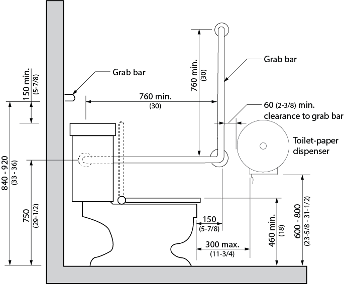
Figure 4.2.3.1 Grab Bar Configuration
4.2.3 - Related Sections
4.1.1 Space and Reach Requirements
4.2.2 Toilet Stalls
4.2.9 Grab Bars
4.4.2 Controls and Operating Mechanisms
4.4.13 Lighting
4.4.15 Texture and Colour
4.2.4 - Lavatories
4.2.4 - Rationale
- The accessibility of lavatories will be greatly influenced by their operating mechanisms. While faucets with remote-eye technology may initially confuse some individuals, their ease of use is notable. Individuals with hand strength or dexterity difficulties can use lever-style handles. For an individual in a wheelchair, a lower counter height and clearance for knees under the counter would be required. This lower counter may also serve children. The insulating of hot water pipes protects the legs of an individual using a wheelchair. This is particularly important when a disability impairs sensation such that the individual would not sense that their legs were being burned. The combination of shallow sinks and higher water pressures can cause unacceptable splashing at lavatories.
4.2.4 - Application
- All lavatories shall comply with this section. In a retrofit situation where it is technically infeasible to have all lavatories comply with this section, at least one lavatory in each accessible washroom shall comply.
4.2.4 - Design Requirements
- Lavatories shall
- be on an accessible route complying with 4.1.4;
- be mounted so that the minimum distance between the centre line of the fixture and the side wall is 460 mm (18-1/8 in.);
- have the top located between 820 mm (32-1/4 in.) and 840 mm (33 in.) above the floor;
- have a knee space of at least
- 920 mm (36 in.) wide;
- 735 mm (29 in.) high at the front edge;
- 685 mm high (27 in.) at a point 200 mm (8 in.) back from the front edge; and
- 350 mm (14 in.) high over the distance from a point 280 mm (11 in.) to the wall;
- have a minimum clear floor space 760 mm wide (30 in.) and 1370 mm (54 in.) deep, of which a maximum of 480 mm (18-7/8 in.) in depth may be under the lavatory;
- have hot water and drain pipes insulated if they abut the clearances noted above, limit the water temperature to a maximum of 43 degrees Celsius (100 degrees F), or use offset drain pipes so they do not enter into the kneespace below the lavatory; and
- have soap and towel dispensers that are
- located to be accessible to persons who use wheelchairs or scooters (i.e., not having to reach over the lavatory to access the devices);
- located so that the dispensing height is between 900 - 1100 mm (35-1/2 - 43-1/4 in.) above the floor and located not more than 610 mm (24 in.) from edge of the lavatory;
- operable with one hand;
- colour-contrasted from the surrounding environment; and
- in compliance with 4.4.2.
- Faucets and other controls shall
- be in compliance with 4.4.2;
- have lever-style handles operable with a closed fist, or be electronically controlled;
- does not require the application of continuous force to maintain water flow;
- where metered, provides at least 10 seconds of water flow; and
- be located so that the distance from the centre line of the faucet to the edge of the basin, or where the basin is mounted in a vanity, to the front edge of the vanity is not more than 485 mm (19-1/8 in.).
- The front apron of a vanity shall have a minimum clearance of 760 mm (30 in.) wide by 735 mm (29 in.) high.
- Shelves or other projections shall;
- be located as not to present a hazard to children or persons with vision loss/no vision;
- be located not more than 200 mm (8 in.) above the surface of the lavatory;
- be not more than 1100 mm (43-1/4 in.) above the finished floor; and
- project no more than 100 mm (4 in.) from the wall.
- Where mirrors are provided at lavatories or vanity units, they shall comply with 4.2.6.
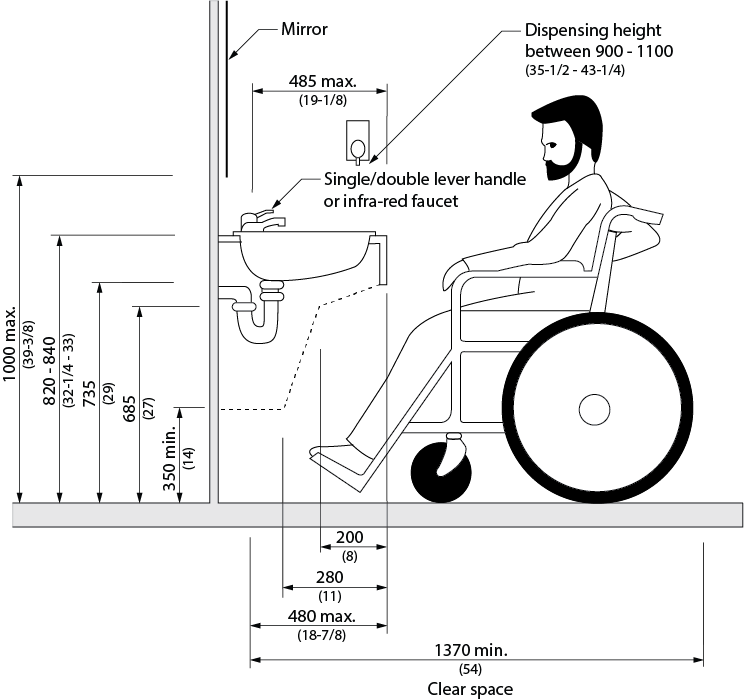
Figure 4.2.4.1 Lavatory Criteria
4.2.4 - Related Sections
4.1.1 Space and Reach Requirements
4.4.2 Controls and Operating Mechanisms
4.4.13 Lighting
4.4.15 Texture and Colour
4.2.5 - Urinals
4.2.5 - Rationale
- A clear floor space is required in front of urinals to manoeuvre a mobility device. The provision of grab bars may assist an individual in rising from a seated position and to steady themselves. Floor-mounted urinals accommodate children and persons of short stature as well as enable easier access to drain personal care devices. Flush controls should be lever-style or automatic (preferred).
- Strong colour contrasts between the urinal, the wall and the floor will assist persons with vision loss/no vision.
4.2.5 - Application
- Where urinals are provided in an accessible toilet or bathing facility, at least one shall comply with this section.
4.2.5 - Design Requirements
- Urinals shall
- be designed at floor level with no step in front of the fixture;
- be wall-mounted with an elongated rim located no higher than 430 mm (17 in.) above the finished floor or floor-mounted with the rim at the finished floor level;
- be at least 345 mm (13-1/2 in.) deep, measured from the outer face of the urinal rim to the back of the fixture;
- have a clear floor space of 810 mm x 1370 mm (32 in. x 54 in.) positioned perpendicular to, and centred on the urinal to allow for a forward approach that shall adjoin or overlap an accessible route which complies with 4.1.1.
- Urinals shall be at least 345 mm (13-1/2 in.) deep, measured from the outer face of the urinal rim to the back of the fixture.
- Where privacy screens are provided
- they shall be mounted at least 460 mm (18 in.) from the centre line of the urinal;
- they shall incorporate a pronounced colour contrast, to differentiate them from the surrounding environment, with a vertical outer edge that contrasts with the screen and the surrounding environment; and
- there shall be a clearance of at least 50 mm (2 in.) from the grab bar.
- Urinals shall have grab bars installed on each side that
- comply with 4.2.9;
- are not less than 600 mm (23-5/8 in.) long;
- are mounted vertically
- not less than 380 mm (15 in.) and not more than 400 mm (15-3/4 in.) from the centre line of the urinal; and
- has its centre line 1000mm above the finished floor
- Flush controls shall be hand- operated or automatic, mounted between 900 - 1100 mm (35-1/2 - 43-1/4 in.) above the finished floor, and shall comply with 4.4.2.
- Where a washroom contains more than two urinals, one urinal shall be provided specifically for children that is
- installed with the rim no higher than 430 mm (17 in.) from the finished floor: or
- floor-mounted, with the rim level at the finished floor
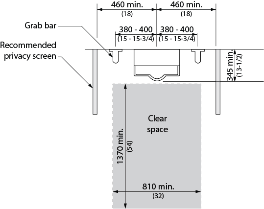
Figure 4.2.5.1 Urinal
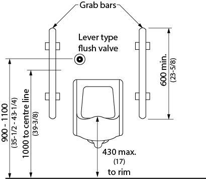
Figure 4.2.5.2 Urinal
4.2.5 - Related Sections
4.1.1 Space and Reach Requirements
4.4.2 Controls and Operating Mechanisms
4.4.13 Lighting
4.4.15 Texture and Colour
4.2.6 - Washroom Accessories
4.2.6 - Rationale
- Design issues related to washroom accessories include the hand strength and dexterity required to operate mechanisms. Reaching the accessories is another concern. Accessories that require the use of two hands to operate can present difficulties for a range of persons with disabilities when the ability to reach or balance is impaired. Section 4.4.2 addresses operating mechanisms in greater detail.
4.2.6 - Application
- Where washroom accessories such as hand-operated dispensers, hand-dryers, built-in garbage receptacles, etc. are provided in a toilet or bathing facility, they shall comply with this section. In a retrofit situation where it is technically infeasible to make all washroom accessories comply with this section, at least one of each type of washroom accessory shall comply in all accessible toilet or bathing facilities.
4.2.6 - Design Requirements
- Each type of washroom accessory provided, unless otherwise specified in 4.2.2 and 4.2.4, shall have operable portions and controls mounted between 900 mm (35-1/2 in.) and 1200 mm (47 in.) above the floor.
- The operable controls and mechanisms of washroom accessories shall comply with 4.4.2.
- Where mirrors are provided, at least one shall be
- mounted with its bottom edge not more than 1000 mm (39-3/8 in.) from the floor; and
- have a minimum mirror height of 1000 mm (39-3.8 in.)
- Tilt mirrors shall not be used.
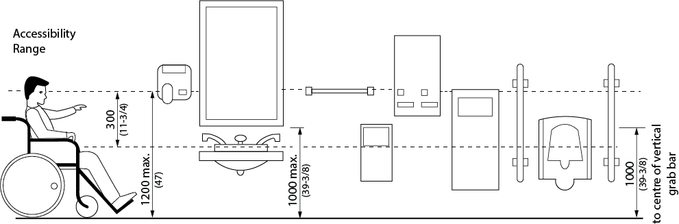
Figure 4.2.6.1 Washroom Accessories
4.2.6 - Related Sections
4.1.1 Space and Reach Requirements
4.1.3 Protruding and Overhead Objects
4.4.2 Controls and Operating Mechanisms
4.4.13 Lighting
4.4.15 Texture and Colour
4.2.7 - Universal Washrooms
4.2.7 - Rationale
- The provision of a separate individual washroom is advantageous in a number of instances. For an individual using a wheelchair, the extra space provided with a separate washroom is preferred to an accessible stall. Should an individual require an attendant to assist them in the washroom then the complication of a woman entering a men’s washroom or vice versa is avoided. This same scenario would apply to a parent with a young child of a different gender.
- In the event of an accident or fall by a single individual in this form of washroom, an emergency call switch and a means of unlocking the door from the outside are important safety features.
4.2.7 - Application
- Universal washrooms shall comply with this section.
- At least one universal washroom, in addition to any accessible public use or common use toilets, shall be provided
- in all public buildings; and
- on every floor level in assembly buildings where the floor incorporates common or public use washroom facilities containing four or more toilet and/or urinal fixtures.
- The minimum number of universal washrooms per building shall be:
- 1 for buildings 1 - 3 storeys;
- 2 for buildings 4 - 6 storeys; or
- 3 for buildings over 6 storeys, plus 1 for each additional increment of 3 storeys.
- If universal washrooms are not visible from the public use or common use toilets, directional signage complying with 4.4.7 shall be provided.
4.2.7 - Design Requirements
- Universal washrooms shall
- be on an accessible route in compliance with 4.1.4;
- be identified with signage in compliance with applicable provisions of 4.4.7;
- be designed to permit a wheelchair to turn within an open space that has a diameter of not less than 2440 mm (96 in.). In a retrofit situation where providing the required turning space is technically infeasible, the turning space may be reduced to not less than 2130 mm (84 in.) with priority given to allow enough clear space between the toilet and the lavatory;
- be equipped with a door that
- complies with 4.1.6;
- is equipped with a power operator;
- can be locked from the inside
- with a closed fist;
- without tight grasping, pinching or twisting of the wrist; and
- with a force less than 22 N (5lbf);
- has latch operating and locking mechanisms located not less than 900 mm (35-1/2 in.) and not more than 1000 mm (39-3/8 in.) above the floor;
- where equipped with a power locking mechanism, have:
- a push-to-lock button on the inside;
- a push-to-unlock button on the inside that also activates the power door operator;
- signage indicating the door locking/unlocking procedures installed next to the locking/unlocking buttons;
- a sign on the inside that is illuminated with the word “LOCKED” when the door is locked; and
- a sign on the outside that is illuminated with the words “IN USE” when the door is locked;
- can be released from the outside or other means provided for door to be opened from the outside in case of emergency;
- be provided with a lavatory conforming to 4.2.4;
- be equipped with a toilet fixture conforming to 4.2.3;
- be equipped with flush controls and other elements conforming to 4.2.3;
- be equipped with grab bars conforming to 4.2.3 and 4.2.9;
- have fixture clearances conforming to 4.2.3 and 4.2.4;
- provided with a clear transfer space adjacent to the toilet fixture, as required by 4.4.7;
- be equipped with
- a collapsable coat hook mounted not more than 1200 mm (47 in.) from the floor on a side wall and projecting not more than 50 mm (2 in.) from the wall;
- a mirror and washroom accessories complying with 4.2.6; and
- a shelf mounted not more than 1200 mm (47 in.) above finished floor;
- have lighting controlled by a motion sensor; and
- where provided, drop-down grab bars shall comply with 4.2.3.
- Universal washrooms shall incorporate an emergency call system linked to an on-site central monitoring location. The emergency call (where applicable) shall also
- be equipped with audible and visual signals both inside and outside washroom;
- be activated by a control device inside washroom typically within reach of the toilet; and
- have a sign that reads IN THE EVENT OF EMERGENCY PUSH EMERGENCY BUTTON AND AUDIBLE AND VISUAL SIGNAL WILL ACTIVATE in letters at least 25 mm (1 in.) high with a 5 mm (1/4 in) stroke and that is posted above the emergency button.
- For park washrooms, where there is no connection to a central monitoring location, localized visual and audible alarms shall be provided.
- Universal washrooms shall incorporate a change table
- at least 810 mm (32 in.) wide by 1830 (72 in.) long;
- with an adjustable surface height range of 450 - 500 mm (17-3/4 in. to 19-5/8 in.) at low range and 850 - 900 mm (33 - 35-1/2 in.) at high range;
- with an adjacent clear floor space not less than 900 mm (35-1/2 in.) along the entire length of the change table;
- designed to carry a minimum load of 1.33 kN (300 lbs.);
- located on an accessible route in compliance with 4.1.4; and
- if of the fold-down type, have no operable portions higher than 1200 mm (47 in.).
- Exception: Where another universal washroom with an adult-sized change table is provided on the same floor level within 45m (147 ft. 8 in.).
Exception: A fixed adult change table may be installed in a park washroom building.
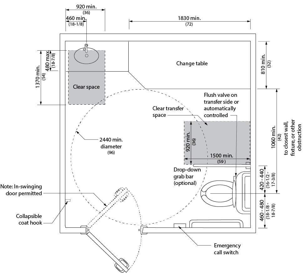
Figure 4.2.7.1 Universal Washroom
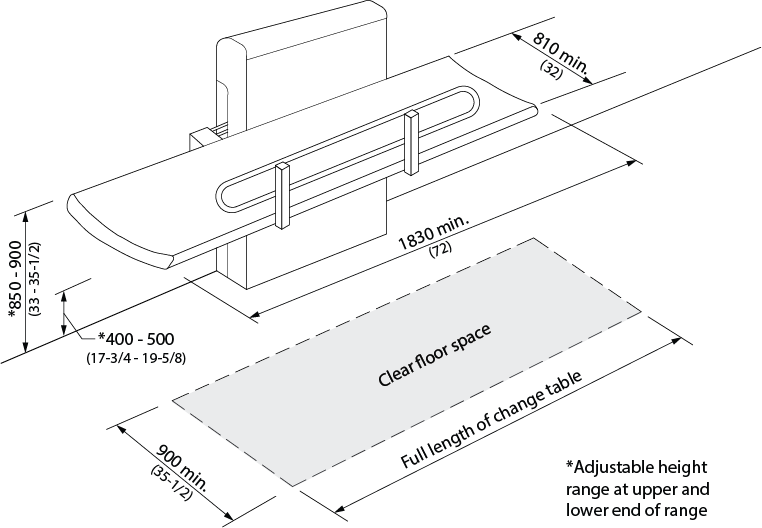
Figure 4.2.7.2 Adult Change Table
- Optional:
- be equipped with a fold-down grab bar at least 760 mm (30 in.) in length at the open side of the toilet, mounted 420 - 440 mm (16-1/2 - 17-3/8 in.) from the centre line of the toilet and 630 - 690 mm (24-3/4 - 27-1/8 in.) above the floor.
4.2.7 - Related Sections
4.1.1 Space and Reach Requirements
4.1.2 Ground and Floor Surfaces
4.1.3 Protruding and Overhead Objects
4.1.6 Doors
4.2.3 Toilets
4.2.4 Lavatories
4.2.5 Urinals
4.2.6 Washroom Accessories
4.2.9 Grab Bars
4.4.2 Controls and Operating Mechanisms
4.4.7 Signage
4.4.11 Card Access, Safety and Security Systems
4.4.12 Glare and Light Sources
4.4.13 Lighting
4.4.14 Materials and Finishes
4.4.15 Texture and Colour
4.2.8 - Showers
4.2.8 - Rationale
- Roll-in or curbless shower stalls eliminate the hazard of stepping over a threshold and are essential for persons with disabilities who use wheelchairs or other mobility devices in the shower. Grab bars and non-slip materials are safety measures which will support any individual. Additional equipment such as a hand-held shower head or a water-resistant folding bench, may be an asset to someone with a disability but also convenient for others. Equipment that contrasts in colour from the shower stall itself will assist individuals with vision loss/no vision.
4.2.8 - Application
- Where showers are provided, at least one shower shall comply with this section.
- Where more than 7 showers are provided, accessible showers shall be provided in conformance with Table 4.2.8.
| # of Showers | # of Showers Required to be Accessible |
|---|---|
| 1 - 7 | 1 |
| Over 7 | 2 plus 1 for each increment of 7 showers. |
4.2.8 - Design Requirements
- Accessible showers shall
- be on an accessible route complying with 4.1.4;
- be at least 1525 mm (60 in.) in width and 920 mm (36 in.) in depth;
- have a clear floor space at the entrance to the shower of at least 920 mm (36 in.) in depth and the same width as the shower, except that fixtures are permitted to project into that space, provided access to the shower is not restricted;
- have a slip-resistant floor surface, sloped no steeper than 1:100 (1%);
- have
- no threshold; or
- a bevelled threshold not exceeding 13 mm (1/2 in.) above the finished floor;
- have a trench-style drain system across the entry to the shower that is colour contrasted to surrounding elements, or other measures to contain water within the shower area;
- be equipped with a water-resistant wall-mounted folding seat that is not spring-loaded or a water-resistant fixed seat that is
- mounted on the same side wall as the vertical grab bar
- not less than 450 mm (17-3/4 in.) wide and 400 mm (15 in.) deep;
- mounted 460 - 480 mm (18 - 19 in.) above the floor;
- designed to carry a minimum load of 1.33 kN (300 lbs.);
- located within 500 mm (19-5/8 in.) of shower controls; and
- has a smooth and slip-resistant surface with no rough edges;
- be equipped with an L-shaped grab bar that
- conforms to 4.2.9;
- is located on the wall opposite the entrance to the shower;
- is located between the shower head and the controls;
- has a horizontal component at least 1000 mm (39-3/8 in.) long mounted between 750 - 870 mm (29-1/2 - 34-1/4 in.) above the finished floor; and
- has a vertical component at least 760 mm (30 in.) long mounted between 400 - 500 mm (15-3/4 - 19-5/8 in.) from the side wall on which the seat is located.
- be equipped with a vertical grab bar on each end wall that
- is at least 1000 mm (39-3/8 in.) in length;
- is mounted 50 - 80 mm (2 - 3-1/8 in.) from the adjacent clear floor area, with the lower end between 600 - 650 mm (23-5/8 and 25-1/2 in.) above the finished floor; and
- conform to 4.2.9;
- be equipped with a pressure-equalizing or thermostatic-mixing valve in compliance with 4.4.2, located above the grab bar but no higher than 1000 mm (39-3/8 in.), maximum 685 mm (27 in.) from the seat wall;
- have fully recessed soap holder(s) which can be reached from the seated position; and
- be equipped with a shower head
- that can be used in a fixed position at a height of 1200 mm (47 in.) and 2030 mm (80 in.) from the finished floor;
- with at least 1800 mm (70-7/8 in.) of flexible hose that can be used both as a fixed position shower head and as a hand held shower head;
- with shower spray unit that is reachable from the seated position;
- that does not obstruct the use of the grab bars; and
- has an on/off control.
- Exception: The use of two fixed-height shower heads with the capability of adjusting the direction of water flow is permitted instead of a hand-held spray unit in facilities that may be subject to vandalism. The height of the higher shower head to be 1825 mm (72 in.). The height of the lower shower head to be 1400 mm (55-1/8 in.). A valve to direct water between the shower heads, in compliance with 4.4.2, shall be located adjacent to the shower control/mixing valve.
- Where the showerhead is mounted on a vertical bar, the bar shall be installed so as not to obstruct the use of the grab bar.
- Enclosures for shower stalls shall not obstruct controls or obstruct transfer from a mobility device onto the shower seat.
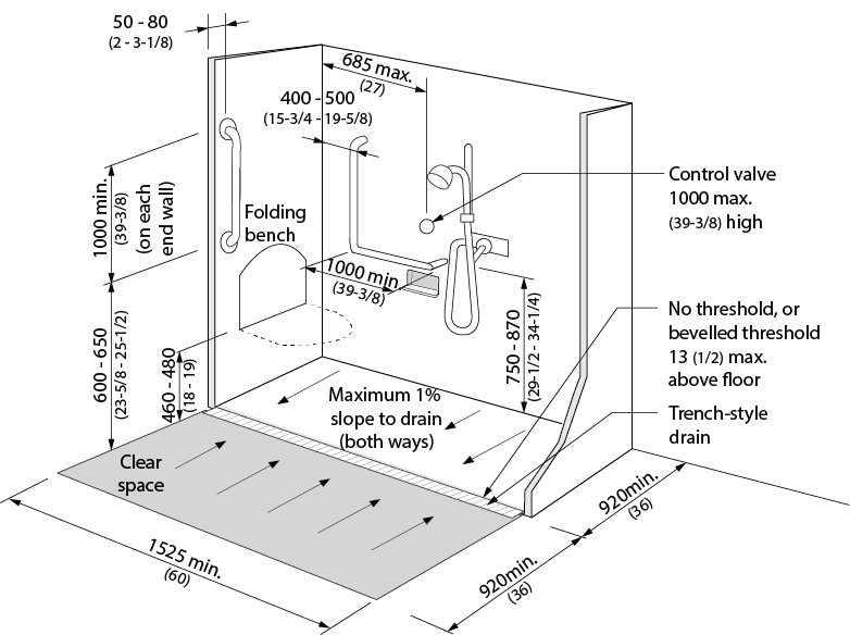
Figure 4.2.8.1 Shower Stall
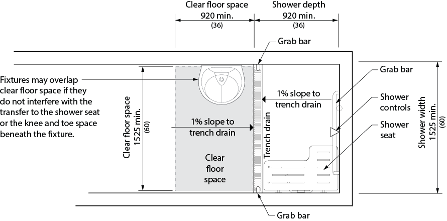
Figure 4.2.8.2 Plan View of Accessible Shower
4.2.8 - Related Sections
4.1.1 Space and Reach Requirements
4.2.6 Washroom Accessories
4.2.9 Grab Bars
4.4.2 Controls and Operating Mechanisms
4.4.13 Lighting
4.4.15 Texture and Colour
4.2.9 - Grab Bars
4.2.9 - Rationale
- Grab bars are an important feature to those who require assistance in standing up, sitting down or stability while standing. Transferring between toilet and wheelchair or scooter may be another scenario where grab bars are utilized.
4.2.9 - Application
- Grab bars shall comply with this section.
4.2.9 - Design Requirements
- Grab bars shall
- be installed to resist a load of at least 1.3 kN (300 lb.), applied vertically or horizontally;
- be not less than 35 mm (1-3/16 in.) and not more than 40 mm (1-9/16 in.) in diameter;
- be free of any sharp or abrasive elements;
- be colour-contrasted with the surrounding environment; and
- have a slip-resistant surface.
- Wall-mounted grab bars shall have a clearance of 50mm (2 in.) to the wall.
- Drop-down grab bars shall comply with 4.2.3.
- Adjacent surfaces shall be free of any sharp or abrasive elements.
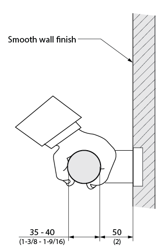
Figure 4.2.9.1 Grab Bar
4.2.9 - Related Sections
4.1.1 Space and Reach Requirements
4.2.3 Toilets
4.2.5 Urinals
4.2.7 Universal Washrooms
4.2.8 Showers
4.4.13 Lighting
4.4.15 Texture and Colour
4.3 - Other Amenities
4.3.1 - Drinking Fountains
4.3.1 - Rationale
- When planning the design of drinking fountains, one should consider the limited height of children and that of a person using a wheelchair or scooter. In the same respect, there may be individuals who have difficulty bending who would require a higher fountain. The operating system should account for limited hand strength or dexterity. The placement of the fountain is also important. Fountains should be recessed, to avoid protruding into the path of travel. Angled recessed alcove designs allow more flexibility and require less precision by a person using a wheelchair or scooter.
4.3.1 - Application
- Where drinking fountains are provided on a floor level, at least one shall be accessible and shall comply with this section. Where more than one drinking fountain or water cooler is provided on a floor level, at least 50% shall be accessible and shall comply with this section.
- Where only one drinking fountain is provided on a floor level, it shall incorporate components that are accessible to individuals who use mobility devices and to those who have difficulty stooping or bending.
4.3.1 - Design Requirements
- Accessible drinking fountains shall
- be located on an accessible route complying with 4.1.4;
- be detectable by a cane at a level at or below 680 mm (26-3/4 in.) from the finished floor;
- be equipped with controls that are located on the front of the unit, or on both sides of the unit, easily operated from a wheelchair or scooter using one hand with a force of not more than 22 N (4.9 lb.), or be automatically operable;
- be mounted with the spout between 760 mm (30 in.) and 900 mm (35-1/2 in.) above the finished floor; and
- project the water stream at least 100 mm (4 in.) high, and at a vertical angle of up to,
- 30 degrees, where the spout is located less than 75 mm (3 in.) from the front of the fountain; or
- 15 degrees, where the spout is located not less than 75 mm (3 in.) and not more than 125 mm (5-7/8 in.) from the front of the fountain.
- Cantilevered drinking fountains shall
- have a clear floor space of at least 810 mm (32 in.) by 1370 mm (54 in.);
- have a knee space between the bottom of the unit and the floor of at least 810 mm (32 in.) wide, 500 mm (19-1/2 in.) deep and 735 mm (29 in.) high;
- have a toe clearance height of at least 350 mm (14 in.) above finished floor, from a point 300 mm (12 in.) back from the front edge to the wall;
- have a depth at the base of the fountain of at least 700 mm (28 in.); and
- be recessed or otherwise located out of the circulation route.
- Freestanding or built-in fountains not having a knee space shall have a clear floor space at least 1370 mm (54 in.) wide by 810 mm (32 in.) deep in front of the unit to accommodate a parallel approach.
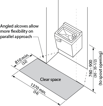
Figure 4.3.1.1 Parallel Approach
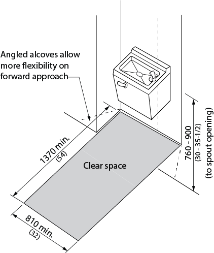
Figure 4.3.1.2 Front Approach
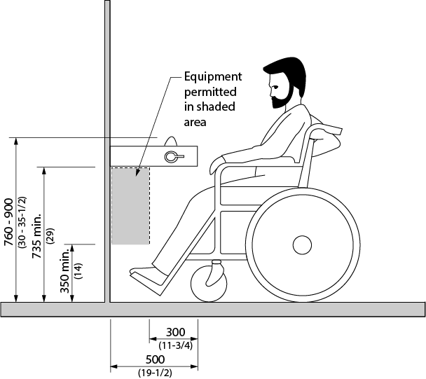
Figure 4.3.1.3 Clearances
4.3.1 - Related Sections
4.1.1 Space and Reach Requirements
4.1.2 Ground and Floor Surfaces
4.1.3 Protruding and Overhead Objects
4.1.4 Accessible Routes, Paths and Corridors
4.4.13 Lighting
4.4.14 Materials and Finishes
4.4.15 Texture and Colour
4.3.2 - Viewing Positions
4.3.2 - Rationale
- Designated viewing areas are required for individuals unable to use typical seating. Viewing areas need to provide adequate space to manoeuvre a mobility device as large as a scooter and should not be limited to one location. Designated companion seating should also be provided. Guards placed around a viewing area should not interfere with the line of sight of someone sitting in a wheelchair or scooter. A choice of seating locations and ticket price range should be available.
- Providing only one size of seating does not reflect the diversity of body types of our society. Seating with increased legroom will better suit individuals that are taller. Seats with removable armrests (adaptable seating) are helpful for persons of larger stature as well as individuals using wheelchairs that prefer to transfer to the seat.
4.3.2 - Application
- In places of assembly occupancy with fixed seating, accessible wheelchair/scooter locations shall comply with this section and shall be provided in numbers as indicated by Table 4.3.2.
- Adaptable seats shall be provided in compliance with Table 4.3.2.
- Spaces for the storage of wheelchairs and other mobility assistive devices shall be provided to accommodate the users of the adaptable seats in compliance with Table 4.3.2.
- Accessible wheelchair/scooter locations shall be an integral part of any seating plan. Seats shall be distributed in a manner that provides people with physical disabilities a choice of admission prices and lines of sight comparable to those for members of the general public.
| Number of Fixed Seats in Seating Area | Minimum number of Spaces Required for Wheelchairs | Minimum number of Adaptable Seats | Minimum number of Storage Facilities for Wheelchairs |
|---|---|---|---|
| Up to 40 | 2 | 2 | 2 |
| 41 - 80 | 3 | 4 | |
| 81 - 100 | 4 | 5 | |
| 101 - 150 | 5 | 5% of all aisle seating | 2 plus 2 for every additional 100 seats |
| 151 - 200 | 6 | ||
| 201 - 300 | 9 | ||
| 301 - 400 | 12 | ||
| 401 - 600 | 15 | ||
| Over 600 | Not less than 3% of the seating capacity |
4.3.2 - Design Requirements
- Accessible wheelchair/scooter locations shall adjoin an accessible route complying with 4.1.4, without infringing on egress from any row of seating or any aisle requirement.
- Accessible wheelchair/scooter locations shall be
- clear and level, or level with removable seats;
- not less than 920 mm (36 in.) wide, and
- minimum 1525 mm (60 in.) long if approaching from the side; or
- minimum 1370 mm (54 in.) if approaching from the front or back;
- where the seating capacity exceeds 100, provided in more than one location;
- arranged to have
- at least 2 of the designated spaces side by side;
- at least one fixed companion seat located beside
- each group of designated spaces, if 2 or more designated spaces are arranged side by side in a group; and
- each designated space that is not part of a group
- located without infringing on egress from any row of seating or aisle; and
- situated as part of the designated seating plan to provide choice of viewing location and clear view of the event taking place.
- Fixed seats designated for adaptable seating shall be
- located without infringing on egress from any row of seating or aisle;
- equipped with moveable or removable arm rest on the side of the seat adjoining the barrier-free path of travel; and
- situated as part of the designated seating plan to provide choice of viewing location and clear view of the event taking place.
- Storage facilities for wheelchairs and other assistive devices shall
- have a minimum floor space of 810 mm (32 in.) by 1370 mm (54 in.) for each device;
- be located on the same level and as close as practicable to the designated seating spaces.
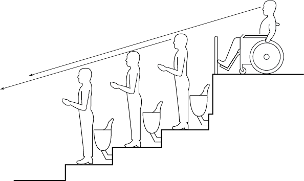
Figure 4.3.2.1 Sight Lines at Wheelchair Locations
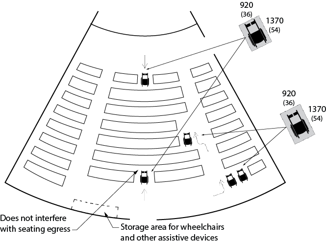
Figure 4.3.2.2 Distribution of Wheelchair Locations
4.3.2 - Related Sections
4.1.1 Space and Reach Requirements
4.1.2 Ground and Floor Surfaces
4.1.3 Protruding and Overhead Objects
4.1.4 Accessible Routes, Paths and Corridors
4.4.6 Assistive Listening Systems
4.4.7 Signage
4.4.9 Public Address System
4.4.14 Materials and Finishes
4.4.15 Texture and Colour
4.4.16 Acoustics
4.3.3 - Elevated Platforms
4.3.3 - Rationale
- Elevated platforms, such as stage areas, speaker podiums, etc., should be accessible to all. A marked accessible route should be provided, along with safety features to assist persons who are visually impaired.
4.3.3 - Application
- Elevated platforms provided for use by the general public, clients, customers or employees shall comply with this section.
4.3.3 - Design Requirements
- Elevated platforms shall
- be located on an accessible route that complies with 4.1.4;
- be capable of being illuminated to at least 100 lux (9.3 ft-candles) at floor level at the darkest point;
- be sized to safely accommodate wheelchairs and other mobility equipment in compliance with 4.1.1; and
- where more than 250 mm (10 in.) above the ground or floor surface and not protected by a guard, have a detectable warning surface.
- A ramp shall be provided for stages in compliance with section 4.1.9.
- The detectable warning surface on elevated platforms shall
- be positioned parallel to the open platform edge, extending the full length of the platform; and
- be a minimum depth of 610 mm (24 in.) and a maximum of 920 mm (36 in.), flush from the open edge of the platform.
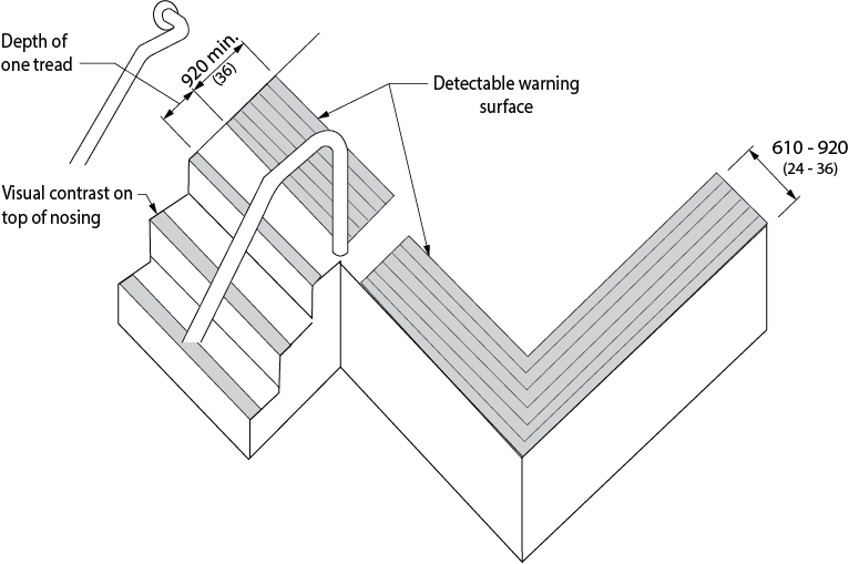
Figure 4.3.3.1 Detectable Warning Surfaces at Elevated Platform
4.3.3 - Related Sections
4.1.1 Space and Reach Requirements
4.1.2 Ground and Floor Surfaces
4.1.3 Protruding and Overhead Objects
4.1.4 Accessible Routes, Paths and Corridors
4.1.9 Ramps
4.4.8 Detectable Warning Surfaces
4.4.13 Lighting
4.4.14 Materials and Finishes
4.4.15 Texture and Colour
4.3.4 - Change/Dressing Rooms
4.3.4 - Rationale
- In addition to accessible common use dressing rooms, a separate unisex dressing room is useful. This is valuable in a scenario where an attendant of the opposite sex or a parent is assisting a child. Sufficient space should be allowed for two people and a wheelchair, along with benches and accessories.
- The provision of handrails along circulation routes from dressing rooms to pool, gymnasium and other activity areas, will be of benefit to many facility users.
4.3.4 - Application
- Where dressing rooms are provided for use by the general public, patients, customers, performers or employees, they shall comply with this section. In a retrofit situation where it is technically infeasible to have all dressing rooms comply with this section, 10% of dressing rooms, but never less than one, for each type of use in each cluster of dressing rooms shall be accessible and comply with this section.
- At least one private accessible dressing room shall be provided within accessible change rooms at pools, gymnasiums and other applicable facilities.
4.3.4 - Design Requirements
- Accessible dressing rooms, and accessible elements within accessible dressing rooms, shall be located on an accessible route complying with 4.1.4.
- Accessible dressing rooms shall be labeled with the international symbol of accessibility.
- Private accessible dressing rooms shall incorporate a clear floor space allowing a person using a wheelchair or scooter to make a 180-degree turn, accessed through either a hinged or sliding door. No door shall swing into any part of the required turning space within the private accessible dressing room. Turning space is not required within a private accessible dressing room accessed through a curtained opening of at least 950 mm (37-1/2 in.) wide, if clear floor space complying with section 4.1.1 renders the dressing room usable by a person in a wheelchair or scooter.
- All doors to accessible dressing rooms shall be in compliance with 4.1.6. Outward swinging doors shall not constitute a hazard to persons using adjacent circulation routes.
- Every accessible dressing room shall have a 810 mm (32 in.) x 1830 mm (72 in.) bench fixed to the wall along the longer dimension. The bench shall
- be mounted 450 to 500 mm (17-3/4 in. to 19-5/8 in.) above the finished floor;
- have clear floor space at least 760 mm (30 in.) wide provided alongside the bench to allow a person using a wheelchair or scooter to make a parallel transfer onto the bench; and
- be designed to carry a minimum load of 1.33 kN (300 lb.).
- Where coat hooks are provided, they shall be a collapsible-style projecting not more than 50 mm (2 in.) from the wall. At least two collapsible coat hooks shall be mounted no higher than 1200 mm (47 in.) above the floor, and immediately adjacent to the accessible bench. (Note: Coat hooks should NOT be located over the accessible bench or in areas that may cause a hazard.)
- To enable transfer to the bench, grab bars similar to those in section 4.2.8 Showers shall be provided in a suitable location in the dressing room.
- Where dressing rooms are provided in conjunction with showers, swimming pools, or other wet locations, they shall
- be designed with a slip-resistant floor surface that prevents the accumulation of standing water; and
- have a bench with a slip-resistant seat surface installed to prevent the accumulation of water.
- Where mirrors, or other reflective surfaces, are provided in dressing rooms of the same use, accessible dressing rooms shall incorporate a full-length mirror or other reflective surface measuring at least 460 mm (18 in.) wide by 1370 mm (54 in.) high and shall be mounted in a position affording a view to a person on the bench, as well as to a person in a standing position.
- Dressing rooms shall incorporate even illumination throughout of at least 100 lux (10 ft-candles).
- For open area large group change areas (such as locker rooms) refer to section 4.3.10.
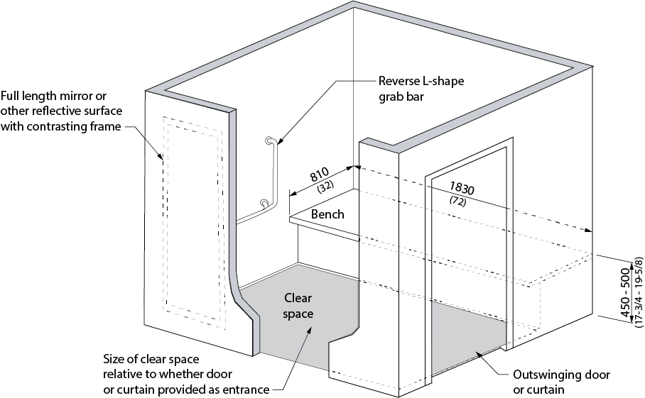
Figure 4.3.4.1 Private Accessible Dressing Room
4.3.4 - Related Sections
4.1.1 Space and Reach Requirements
4.1.2 Ground and Floor Surfaces
4.1.3 Protruding and Overhead Objects
4.1.4 Accessible Routes, Paths and Corridors
4.4.13 Lighting
4.4.14 Materials and Finishes
4.4.15 Texture and Colour
4.3.5 - Offices, Work Areas and Meeting Rooms
4.3.5 - Rationale
- Offices providing services or programs to the public should be accessible to all, regardless of mobility or functional profile. Furthermore, office and related support areas should be accessible to staff and visitors with varying levels of ability.
- All persons, but particularly those with hearing loss/persons who are hard-of-hearing, would benefit from having a quiet acoustic environment - background noise from mechanical equipment such as fans, should be minimal. Telephone equipment for individuals with hearing loss may also be required.
- The provision of assistive speaking devices is important for the range of individuals who may have difficulty with low vocal volume thus affecting production of normal audible levels of sound.
- Tables and workstations should address the knee space requirements of an individual in a wheelchair. Circulation areas also need to consider the spatial needs of mobility equipment as large as scooters.
- Natural coloured task lighting, such as that provided through halogen bulbs, is a design feature that will facilitate use by all, especially persons with vision loss/no vision.
- In locations where reflective glare may be problematic, such as large expanses of glass with reflective flooring, consideration should be given to providing blinds that can be louvred upwards.
4.3.5 - Application
- Wherever offices, work areas or meeting rooms are provided for use by the general public, employees, clients or customers, they shall comply with this section.
- Where multiple workstations are provided, at least 5% but not less than one shall have height adjustable worksurfaces.
4.3.5 - Design Requirements
- Where offices, work areas and meeting rooms are provided for use by the general public, employees, clients or customers, they shall
- be located on an accessible route complying with 4.1.4;
- where equipped with a door, the door shall comply with 4.1.6;
- incorporate a clear floor space allowing a person using a wheelchair or scooter to make a 180-degree turn;
- incorporate an accessible route that connects the primary activity elements within the office, work area or meeting room;
- incorporate knee clearances below work surfaces that comply with 4.3.7;
- incorporate access to storage, shelving or display units in compliance with 4.3.9 for use by the general public, employees, clients or customers;
- provide a clear floor space that complies with 4.1.1 in front of all equipment such as photocopiers where such equipment is provided for use by the general public, employees, clients or customers;
- be equipped with an assistive listening system that complies with 4.4.6, where an assistive listening system is required; and
- provide one of the following: gooseneck fixed microphone at designated seating area, cordless microphone or a personal voice amplification system.
4.3.5 - Related Sections
4.1.1 Space and Reach Requirements
4.1.2 Ground and Floor Surfaces
4.1.4 Accessible Routes, Paths and Corridors
4.1.8 Windows, Glazed Screens and Sidelights
4.3.7 Tables, Counters and Work Surfaces
4.3.9 Storage, Shelving and Display Units
4.4.2 Controls and Operating Mechanisms
4.4.4 Visual Alarms
4.4.6 Assistive Listening Systems
4.4.12 Glare and Light Sources
4.4.13 Lighting
4.4.14 Materials and Finishes
4.4.15 Texture and Colour
4.4.16 Acoustics
4.3.6 - Waiting and Queuing Areas
4.3.6 - Rationale
- Queuing areas for information, tickets or services should permit persons who use wheelchairs, scooters and other mobility devices as well as persons with a varying range of user ability to move through the line safely and conveniently.
- Waiting and queuing areas need to provide space for mobility devices, such as wheelchairs and scooters. Queuing lines that turn corners or double back on themselves will need to provide adequate space to manoeuvre mobility devices. Providing handrails in queuing lines may be useful support for individuals and guidance for those with vision loss/no vision. The provision of benches in waiting areas is important for individuals who may have difficulty with standing for extended periods.
4.3.6 - Application
- In addition to the design requirements specified in 4.1 to 4.4, waiting and queuing areas shall comply with this section.
4.3.6 - Design Requirements
- Barriers at queuing areas shall be laid out in parallel, logical lines. The accessible path of travel between fixed queuing lines and barriers shall comply with 4.1.4.
- Barriers at queuing areas, provided to streamline pedestrian movement, shall be firmly mounted to the floor, and should have rigid rails to provide support for waiting persons.
- Where floor slots or pockets are included to receive temporary or occasional supports, such slots or pockets shall be level with the floor finish and have an integral cover, so as not to cause a tripping hazard.
- Permanent queuing areas shall incorporate clearly defined floor patterns/colours/textures in compliance with 4.4.15, as an aid to guide persons with vision loss/no vision.
- There shall be a pronounced colour contrast between ropes, bars or solid barriers used to define queuing areas and the surrounding environment.
- Provide sufficiently clear floor area to permit mobility aids to turn where queuing lines change direction (refer to figures 4.1.4.3 and 4.1.4.4).
- Fixed queuing guides must be cane detectable.
- In waiting rooms where seating is fixed to the floor, a minimum of 3% but no less than 1 seat of the total seating must provide the clear floor space for mobility devices as defined in section 4.3.2. Accessible seating shall have an adjacent companion seat.
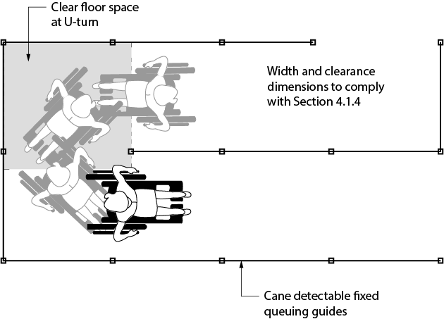
Figure 4.3.6.1 Fixed Queuing Guides
4.3.6 - Related Sections
4.1.1 Space and Reach Requirements
4.1.2 Ground and Floor Surfaces
4.1.4 Accessible Routes, Paths and Corridors
4.4.5 Public Telephones
4.4.6 Assistive Listening Systems
4.4.7 Signage
4.4.9 Public Address Systems
4.4.10 Information Systems
4.4.12 Glare and Light Sources
4.4.13 Lighting
4.4.14 Materials and Finishes
4.4.15 Texture and Colour
4.4.16 Acoustics
4.3.7 - Tables, Counters and Work Surfaces
4.3.7 - Rationale
- Tables, counters and work surfaces should accommodate the needs of a range of users. Consideration should be given to standing-use as well as seated use. For individuals using wheelchairs, tables need to be high enough to provide knee space and provide enough clear space for the wheelchair to pull into. The furniture placement at tables and manoeuvring space at counters should provide sufficient turning space for a person using a wheelchair or scooter.
- Tables that have the support leg(s) in the centre of the table provide a higher level of accessibility.
4.3.7 - Application
- If fixed or built-in tables, counters and work surfaces (including, but not limited to, dining tables and study carrels) are provided in accessible public or common use areas, at least 10%, but not less than one, of the fixed or built-in tables, counters and work surfaces shall comply with this section.
- It is preferred to locate counters out of the circulation route so they do not become an obstacle for persons who use canes and or persons with vision loss/no vision.
- Ensure that chairs with armrests are provided for banquet halls, restaurants and cafeterias.
4.3.7 - Design Requirements
- Accessible tables, counters and work surfaces shall be located on an accessible route complying with 4.1.4.
- An accessible route complying with 4.1.4 shall lead to and around such fixed or built-in tables, counters and work surfaces.
- Wheelchair seating spaces at accessible tables, counters and work surfaces shall incorporate a clear floor space that
- is at least 810 mm (32 in.) x 1370 mm (54 in.); and
- has no more than 480 mm (18-7/8 in.) of the length extending under the counter or work surface where a forward approach is used.
- Where a forward approach is used to access a wheelchair seating space,
- a clear knee space of at least 810 mm (32 in.) wide, 480 mm (18-7/8 in.) deep and 685 mm (27 in.) high shall be provided; and
- a clear toe space at least 810 mm (32 in.) wide and 230 mm (18-7/8 in.) high shall be provided beyond the knee space, extending to a depth at least 610 mm (24 in.) from the front edge of the work surface.
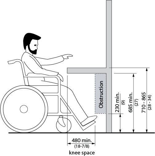
Figure 4.3.7.1 Clearances
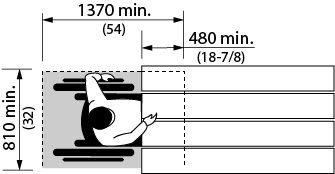
Figure 4.3.7.2 Frontal Approach
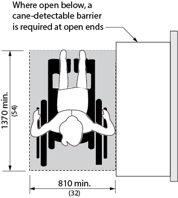
Figure 4.3.7.3 Parallel Approach
- The top of accessible tables, counters and work surfaces shall be located between 710 mm (28 in.) to 865 mm (34 in.) above the finished floor or ground surface. It is preferred to provide height-adjustable furnishings.
- Where speaker podiums are provided they shall
- be located on an accessible route in compliance with 4.1.4;
- be height-adjustable for use from a seated or standing position;
- incorporate clear floor space of at least 810 mm (32 in.) by 1370 mm (54 in.), configured for forward approach;
- incorporate clear knee space of at least 810 mm (32 in.) wide, 480 mm (18-7/8 in.) deep and 685 mm (27 in.) high; and
- incorporate controls and operating mechanisms in compliance with 4.4.2.
4.3.7 - Related Sections
4.1.1 Space and Reach Requirements
4.1.3 Protruding and Overhead Objects
4.1.4 Accessible Routes, Paths and Corridors
4.3.8 - Information, Reception and Service Counters
4.3.8 - Rationale
- Information, reception and service counters should be accessible to the full range of visitors. A choice of counter heights is recommended to provide a range of options for a variety of persons. Lowered sections will serve children, persons of short stature and persons using mobility devices such as a wheelchair or scooter. The choice of heights should also extend to speaking ports and writing surfaces.
- The provision of knee space under the counter facilitates use by a person using a wheelchair or a scooter.
- The provision of assistive speaking devices is important for the range of individuals who may have difficulty with low vocal volume thus affecting production of normal audible levels of sound.
- The use of colour contrast, tactile difference or audio landmarks (e.g., receptionist voice or music source) can assist individuals with vision loss/no vision to more precisely locate service counters or speaking ports.
4.3.8 - Application
- Counters for information or service shall have at least one section accessible to persons who use a wheelchair or scooter.
- For each type of service provided, at least 1 accessible service counter shall be provided.
- Where there are multiple queuing lines serving multiple service counters, the accessible service counters must be clearly identified by signage.
- Where a single queuing line serves a single or multiple counters, each service counter shall comply with this section.
4.3.8 - Design Requirements
- Information, reception and service counters shall be located on an accessible route complying with 4.1.4.
- Counters for information, reception or service shall incorporate at least one accessible section that
- has a counter height located between 710 mm (28 in.) and 865 mm (34 in.) above the finished floor or ground;
- has a counter surface width of at least 920 mm (36 in.);
- has a counter depth of no more than 1270 mm (50 in.) that complies with 4.1.1; and
- has knee space on both sides of the counter, below the counter surface, of at least 685 mm (27 in.) high by 480 mm (18-7/8 in.) deep by 810 mm (32 in.) wide.
- Wheelchair seating spaces at accessible sections of information, reception and service counters shall incorporate a clear floor space not less than 760 mm (30in.) by 1370 mm (54 in.).
- Where a forward approach is used to access a wheelchair seating space, a clear knee space of at least 810 mm (32 in.) wide, 480 mm (18-7/8 in.) deep and 685 mm (27 in.) high shall be provided. It may overlap the clear floor space by a maximum of 480 mm (18-7/8 in.).
- Information, reception and service counters shall provide at least one type of Assistive Speaking Device at each counter of varying heights:
- Speech Transfer Intercom System with volume controls for both staff and customers - this can be in a counter system or speaking port;
- gooseneck or cordless microphone; or
- telephone system with voice/speech amplification.
- Where speaking ports are provided at information, reception or service counters, accessible counters shall have a speaking port no higher than 1060 mm (42 in.) above the finished floor or ground.

Figure 4.3.8.1 Service Counter
4.3.8 - Related Sections
4.1.1 Space and Reach Requirements
4.1.4 Accessible Routes, Paths and Corridors
4.4.6 Assistive Listening Systems
4.4.7 Signage
4.4.10 Information Systems
4.4.12 Glare and Light Sources
4.4.13 Lighting
4.4.14 Materials and Finishes
4.4.15 Texture and Colour
4.4.16 Acoustics
4.3.9 - Storage, Shelving and display Units
4.3.9 - Rationale
- The heights of storage, shelving and display units should address a full range of vantage points including the lower sightlines of children or a person using a wheelchair or scooter. The lower heights also serve the lower reach of these individuals. Displays that are too low can be problematic for individuals that have difficulty bending down. Appropriate lighting and colour contrast is particularly important for persons with vision loss/no vision.
4.3.9 - Application
- If fixed or built-in storage facilities, such as cabinets, closets, shelves and drawers, are provided in accessible spaces, at least one of each type provided shall contain storage space in compliance with this section.
- Shelves or display units allowing self-service by customers in mercantile occupancies shall be located on an accessible route complying with 4.1.4.
4.3.9 - Design Requirements
- A clear floor space at least 810 mm (32 in.) by 1370 mm (54 in.) complying with 4.1.1 that allows either forward or parallel approach by a person using a wheelchair or a scooter shall be provided at accessible storage facilities.
- Accessible storage spaces shall be within at least one of the reach ranges specified in 4.1.1. Clothes rods or shelves shall be a maximum of 1370 mm (54 in.) above the finished floor for a side approach. Where the distance from the wheelchair to the clothes rod or shelf is 255 – 535 mm (10-21 in.) (as in closets without accessible doors) the height of the rod or shelf shall be no more than 1200 mm (47 in.).
- Where coat hooks are provided, they shall all be collapsible coat hooks, mounted no higher than 1200 mm (47 in.) above the floor. (Note: Coat hooks should NOT be located over benches)
- Hardware for accessible storage facilities shall comply with 4.4.2. Touch latches and U-shaped pulls are acceptable.
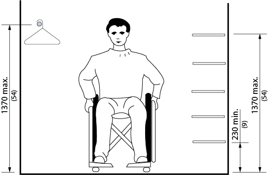
Figure 4.3.9.1 Reach Limits for Storage
4.3.9 - Related Sections
4.1.1 Space and Reach Requirements
4.1.4 Accessible Routes, Paths and Corridors
4.4.2 Controls and Operating Mechanisms
4.3.10 - Lockers and Baggage Storage
4.3.10 - Rationale
- In schools, recreational facilities, transit facilities, etc., or wherever public or private storage lockers are provided, at least some of the storage units should be accessible by a person using a wheelchair or scooter.
- It is preferred to provide an accessible bench in close proximity to accessible lockers.
- The provision of lockers at lower heights serves the reach restrictions of children or a person using a wheelchair or scooter. The operating mechanisms should also be at an appropriate height and operable by individuals with restrictions in hand dexterity (ie. operable with a closed fist).
4.3.10 - Application
- If lockers or baggage storage units are provided in accessible public or common use areas, at least 10%, but not less than one, of the lockers or baggage storage units shall comply with this section.
4.3.10 - Design Requirements
- Accessible lockers and baggage storage units shall be located on an accessible route complying with 4.1.4.
- Accessible lockers and baggage storage units shall have their bottom shelf no lower than 230 mm (9 in.) and their top shelf no higher than 1200 mm (47 in.) above the floor or ground.
- Locks for accessible lockers and baggage storage units shall be mounted no higher than 1060 mm (42 in.) from the floor or ground and shall comply with 4.4.2.
- Unless all lockers are accessible, accessible lockers shall be identified with an International Symbol of Access or equivalent.
- Numbers or names on all lockers and baggage storage units should be in clearly legible lettering, raised or recessed and of a highly contrasting colour or tone (in compliance with the relevant parts of 4.4.7).
- Baggage racks or carousels for suitcases, etc. shall have the platform surface no higher than 460 mm (18 in.) from the floor and shall incorporate a continuous colour-contrasting strip at the edge of the platform surface.
- Aisle spaces in front of lockers, baggage compartments and carousels should be a minimum of 1370 mm (54 in.) deep and 810 mm (32 in.) wide, to permit forward and lateral approach by a person using a wheelchair or scooter.
- Where an accessible bench is installed near accessible lockers, grab bars shall be installed where practicable.
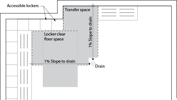
Figure 4.3.10.1 Locker Room Clear Floor Space Requirements
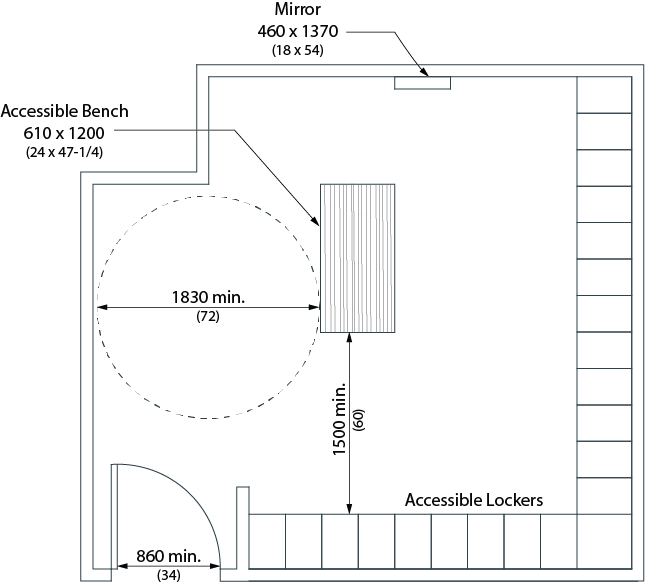
Figure 4.3.10.2 Locker Room Sample Layout
4.3.10 - Related Sections
4.1.1 Space and Reach Requirements
4.1.4 Accessible Routes, Paths and Corridors
4.4.2 Controls and Operating Mechanisms
4.4.7 Signage
4.4.13 Lighting
4.4.15 Texture and Colour
4.3.11 - Roof-top Patios, Balconies, Porches, Terraces and Patios
4.3.11 - Rationale
- Where a number of roof-top patios, balconies, porches, patios or terraces are provided, it is desirable to consider options for different levels of sun and wind protection. This is of benefit to individuals with varying tolerances for sun or heat. Doors to these spaces typically incorporate large expanses of glazing. These should be appropriately marked to increase their visibility. Thresholds at balcony doors should be avoided.
4.3.11 - Application
- Roof-top patios, balconies, porches, terraces and patios provided for use by the general public, clients, customers or employees shall comply with this section.
4.3.11 - Design Requirements
- Roof-top patios, balconies, porches, terraces and patios
- shall be located on an accessible route complying with 4.1.4;
- shall have a minimum depth of 2440 (96 in.). In retrofit situations where providing a depth of 2440 mm (96 in.) is technically infeasible, the minimum depth may be reduced to 1525 mm (60 in.); and
- where an out swinging door is used, shall have a minimum depth of 1100 mm (43-1/4 in.) between the door and any adjacent guard or railing.
- Exterior roof-top patios, balconies, porches, terraces and patios, where directly accessible from the interior spaces, shall incorporate a threshold in compliance with 4.1.2.
- Roof-top patio, balcony, porch, terrace and patio surfaces shall
- comply with 4.1.2;
- be sloped to ensure removal of water; and
- be sloped no more than 2%.
- Railings and guards at foor-top patios, balconies, porches, terraces and patios shall
- comply with the requirements of the Ontario Building Code;
- be designed to allow clear vision below the rail for persons seated in a wheelchair or scooter; and
- incorporate pronounced colour contrast between the railings and guards and the surrounding environment.
- Doors opening out onto balconies shall be located to open against a side wall or rail.
4.3.11 - Related Sections
4.1.1 Space and Reach Requirements
4.1.2 Ground and Floor Surfaces
4.1.4 Accessible Routes, Paths and Corridors
4.1.6 Doors
4.4.14 Materials and Finishes
4.4.15 Texture and Colour
4.3.12 - Parking
4.3.12 - Rationale
- The provision of parking spaces near the entrance to a facility is important to accommodate persons with a varying range of abilities as well as persons with limited mobility. Medical conditions, such as arthritis or heart conditions, using crutches or the physical act of pushing a wheelchair, all make it difficult to travel long distances. Minimizing travel distances is particularly important outdoors, where weather conditions and ground surfaces can make travel both difficult and hazardous.
- In addition to the proximity to entrances, the sizes of accessible parking spaces is important. A person using a mobility aid such as a wheelchair requires a wider parking stall to accommodate the manoeuvring of the wheelchair beside the car or van. A van may also require additional space to deploy a lift or ramp through the side or back door. An individual would then require space for the deployment of the lift itself as well as additional space to manoeuvre on/off the lift.
- Heights along the routes to accessible parking is a factor. Accessible vans may have a raised roof resulting in the need for additional overhead clearance. Alternatively, the floor of the van may be lowered, resulting in lower tolerances for speed bumps and pavement slope transitions.
- The number of accessible parking spaces required by this section may not be sufficient in some facilities (such as seniors' centres) where increased numbers of persons with disabilities may be expected. In this situation, the number of accessible parking spaces may be increased from the requirements in this standard.
- Wherever possible locate parking signs away from pedestrian routes, as they may constitute an overhead and/or protruding hazard. It is preferable that the sign be placed at the curb line to denote the end of the parking space.
4.3.12 - Application
- This standard is applicable to all new parking structures and surface parking lots. For existing structures and surface parking lots undergoing renovations/alterations, standards should be employed to the greatest extent possible.
- The number of designated parking spaces shall be in accordance with Table 4.3.12. and shall be located on the shortest possible circulation route, with minimal traffic flow crossing, to an accessible facility entrance (e.g., in lots serving a particular facility) or to an accessible pedestrian entrance of the parking facility (e.g., in lots not serving a particular facility).
- Accessible routes to accessible parking spaces shall be configured to avoid travel behind parked vehicles or along vehicle routes.
- In facilities with multiple accessible entrances with adjacent parking, designated parking spaces shall be dispersed and located closest to the accessible entrances.
- If more than one off-street parking facility is provided, parking requirements shall be calculated individually for each parking facility.
- If more than one off-street parking facility is provided, parking spaces for the use of persons with disabilities shall be distributed among the multiple lots to provide equivalent or greater accessibility in terms of distance from an accessible entrance or user convenience.
| Total Number of Required Parking Spaces | Minimum Number of Required Accessible Parking Spaces |
|---|---|
| 12 or less | 1 |
| 13 - 100 | 4% of the total (1)(2) |
| 101 - 200 | 1 space plus 3% of the total (2) |
| 201 - 1000 | 2 spaces plus 2% of the total (2) |
| more than 1000 | 11 spaces plus 1% of the total (2) |
| (1) Where only 1 accessible parking space is required, a Type A accessible parking space shall be provided. (2) Where more than 1 accessible parking space is required (2.1) if an even number of accessible parking spaces are required, an equal number of Type A and Type B accessible parking spaces must be provided. (2.2)if an odd number of accessible parking spaces are required, an equal number of Type A and Type B accessible parking spaces must be provided and the odd space may be a Type B accessible parking space. |
|
4.3.12 - Design Requirements
- An accessible route shall be provided from each designated parking space to an accessible entrance into the facility.
- Designated accessible parking spaces shall
- be located on an accessible route complying with 4.1.4;
- be provided within 30m (98 ft. 5 in.) of an accessible building entrance;
- have a firm, level surface with a maximum of 1.5% running slope for drainage;
- have a maximum cross slope of 1%;
- have a height clearance of at least 2750 mm (9 ft.) at the parking space and along the vehicle access and egress routes; and
- incorporate signage as outlined in this section.
- Accessible parking spaces shall
- be provided in two sizes;
- Type A shall have an unobstructed rectangular area with a minimum width of 3650 mm (12 ft. ) and a minimum length of 5300 mm (17 ft. 4-1/2 in.);
- Type B shall have an unobstructed rectangular area with a minimum width of 2700 mm (8 ft. 10-1/2 in.) and a minimum length of 5300 mm (17 ft. 4-1/2 in.);
- incorporate pavement markings containing the International Symbol of Access in accordance with Figure 4.4.7.4. Markings to include a 1525 x 1525 (5 ft. x 5 ft.) white border and symbol with a blue background field colour;
- have an adjacent access aisle that
- is at least 1500 mm (59 in.) wide;
- is clearly marked with high tonal contrast diagonal lines;
- may be shared between two spaces (Refer to Figures 4.3.12.1 and 4.3.12.2); and
- where possible, provide the option of access aisles on either side of an accessible parking space; and
- have a height clearance at the parking space and along the vehicle access and egress routes,
- of at least 2750 mm (108 in.) at outdoor parking; and
- of at least 2590 mm (98 in.) at indoor parking, including vehicular entrances.
- be provided in two sizes;
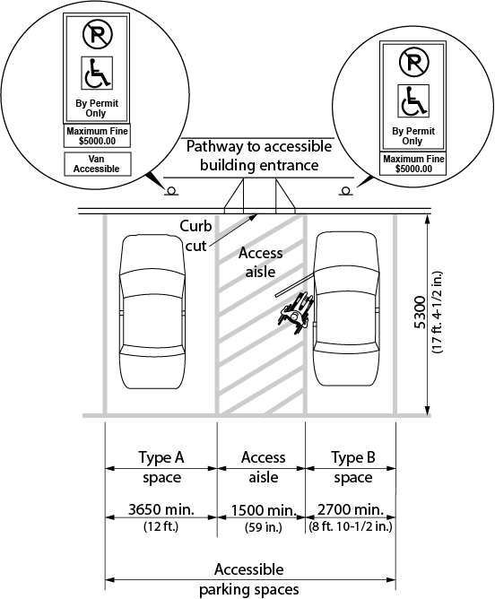
Figure 4.3.12.1 Side-by-side Parking Space
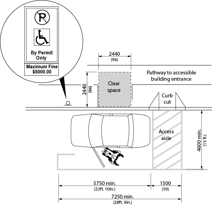
Figure 4.3.12.2 Parallel Parking Space
- Ontario Building Code (OBC) stipulates that the minimum unobstructed height of a below grade parking structure is 2.1m.
- It is preferred that the above dimensions are followed; however, in a retrofit situation where it is technically infeasible, use OBC dimensions.
- Accessible parallel parking stalls should be at least 7250 mm (23ft-10in.) in length and 4600 mm (15 ft.) in width. In a retrofit situation where it it technically infeasible to provide a depth of 4600 mm (15 ft.), the depth may be reduced to match the other parallel parking spaces on the street.
- It is preferred to provide a clear space of at least 2440 mm (96 in.) by 2440 mm (96 in.) at the curb level, adjacent to the passenger side for parallel parking spaces.
- Indoor parking facilities shall incorporate a sign at the vehicle entrance indicating the minimum overhead clearance at the parking space and along the vehicle access and egress routes.
- Signage of accessible parking spaces shall incorporate an official designated accessible parking space sign developed by the Ministry of Transportation (1991).
- Each accessible parking space shall be designated with signage that is
- mounted vertically in a permanent manner;
- if mounted on a post, the post shall be colour contrasted with the background environment;
- at least 300 mm (11-3/4 in.) wide x 450 mm (17-3/4 in.) high;
- installed at a height of 1200 mm (47 in.) from the ground/floor surface to the bottom edge of the sign;
- for perpendicular parking, centred on the parking space; and
- for parallel parking, located toward the end of the parking space, on the opposite side from the access aisle.
- mounted vertically in a permanent manner;
- A second sign to deter illegal usage of the accessible parking space is recommended to be mounted below the regulated sign outlined in figure 4.3.12.4, noting the maximum fine of $5000.
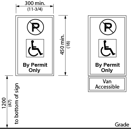
Figure 4.3.12.3 Regulatory Parking Signage
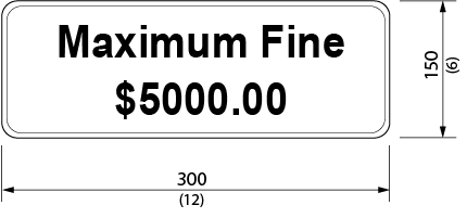
Figure 4.3.12.4 Second accessible Parking Signage
- Where the location of designated parking spaces is not obvious or is distant from the approach viewpoints, directional signage shall be placed along the route leading to the designated parking spaces. Such directional signage shall incorporate the symbol of access and the appropriate directional arrows.
- Where the location of the nearest accessible entrance is not obvious or is distant from the approach viewpoints, directional signs shall be placed along the route leading to the nearest accessible entrance to the facility. Such directional signage will incorporate the symbol of access and the appropriate directional arrows.
- When constructing or redeveloping existing on-street parking spaces, designated public sector organizations shall consult on the need, location and design of accessible on-street parking spaces and shall do so in the following manner:
- Designated public sector organizations must consult with the public and persons with disabilities;
- Municipalities must also consult with their municipal accessibility advisory committees, in accordance with AODA, IASR, Design of Public Spaces Standards, Section 80.39.
- In this section, “designated public sector organization” means every municipality and every person or organization described in Schedule 1 of Ontario Regulation 191/11 (Integrated Accessibility Standards), but not persons or organizations listed in Column 1 of Table 1 to Ontario Regulation 146/10 (Public Bodies and Commission Public Bodies - Definitions) made under the Public Service of Ontario Act, 2006.
4.3.12 - Related Sections
4.1.1 Space and Reach Requirements
4.1.2 Ground and Floor Surfaces
4.1.3 Protruding and Overhead Objects
4.1.4 Accessible Routes, Paths and Corridors
4.1.10 Curb Ramps
4.4.7 Signage
4.4.8 Detectable Warning Surfaces
4.4.13 Lighting
4.4.14 Materials and Finishes
4.4.15 Texture and Colour
4.3.13 - Passenger Loading Zones
4.3.13 - Rationale
- Passenger-loading zones are important features for individuals who may have difficulty in walking distances or those who use parallel transit systems. Accessible transit vehicles typically require space for the deployment of lifts or ramps and overhead clearances. Protection from the elements will be beneficial to all users and particularly those that may have difficulty with mobility.
4.3.13 - Application
- Where passenger-loading zones are provided, at least one shall comply with this section.
- Accessible passenger-loading zones shall be identified with signage complying with applicable provisions of 4.4.7.
- A passenger loading zone typically includes a driveway, a lay-by for the stopped vehicles, the access aisle for the loading and unloading, and the pedestrian path of travel.
- Bollards between the access aisle and the lay-by can be used to prevent vehicles from pulling into the access aisle.
4.3.13 - Design Requirements
- Passenger-loading zones shall
- be on an accessible route complying with 4.1.4;
- provide an access aisle that is
- have a curb ramp complying with 4.1.10 where there are curbs between the access aisle and the vehicle pull-up space; and
- have a minimum vertical clearance of 3600 mm (11 ft. 10 in.) at the loading zone and along the vehicle access route to such areas to and from the site entrances.
- In a retrofit situation where providing a 2440 mm (96 in.) wide access aisle is technically infeasible, the access aisle width may be reduced to 2000 mm (78-3/4 in.).
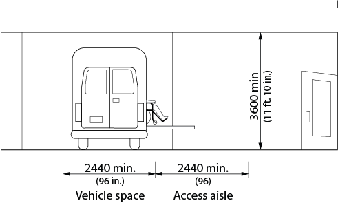
Figure 4.3.13.1 Clearances at Passenger Loading Zone
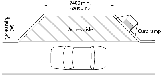
Figure 4.3.13.2 Passenger Loading Zone
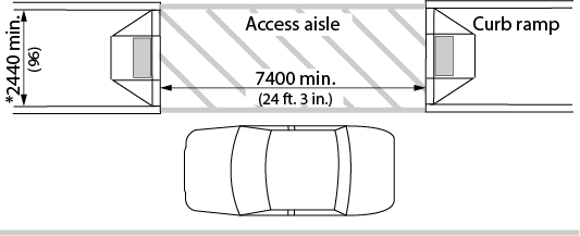
Figure 4.3.13.3 Alternate Passenger Loading Zone Configuration
- * Note: In a retrofit situation where it is technically infeasible to provide the required access aisle width, the aisle width may be reduced to 2000 mm (78-3/4 in.).
4.3.13 - Related Sections
4.1.1 Space and Reach Requirements
4.1.2 Ground and Floor Surfaces
4.1.3 Protruding and Overhead Objects
4.1.4 Accessible Routes, Paths and Corridors
4.1.10 Curb Ramps
4.4.7 Signage
4.4.8 Detectable Warning Surfaces
4.4.13 Lighting
4.4.14 Materials and Finishes
4.4.15 Texture and Colour
4.3.14 - Landscaping Materials and Plantings
4.3.14 - Rationale
- Landscape materials, trees, shrubs and plants should be selected and located with a wide variety of users in mind. For instance, plants and shrubs with a variety of fragrances can provide an interesting orientation cue for persons with vision loss/no vision. Using contrasting flowers near walkways can also be helpful as a guide. Plants with thorns may constitute a walking hazard. Plants that drop large seed pods can present slipping hazards, as well as difficulties for pushing a wheelchair. Plantings and tree limbs that overhang pathways can impede all users and be a particular hazard to an individual with a vision loss/no vision.
- Raised beds can better accommodate persons who use a mobility device or those that have difficulty in bending to enjoy or tend to plantings.
- Where the use of unit pavers as a walking/wheeling surface is provided, maintenance will have to be monitored and addressed to ensure accessibility remains..
4.3.14 - Application
- Landscaping materials and plantings contained within the site shall comply with this section.
- Where plant beds are provided for gardening use of the general public, clients, customers or employees, at least 10% of the area of the plant beds, but not less than one, shall comply with this section.
4.3.14 - Design Requirements
- Accessible plant beds shall be
- located on an accessible route complying with 4.1.4; and
- raised above the adjacent floor or ground surface 460 mm (18 in.) up to 610 mm (24 in.). Dimensions will vary depending on the type of raised bed (i.e. closed in or open underneath). If open underneath, knee clearance will need to be considered. For further guidance refer to document: "Barrier-Free Community Gardening in Waterloo Region: http://chd.region.waterloo.on.ca/en/partnersProfessionals/resources/BarrierFreeGardens_Guide.pdf.
- Where variations in grading immediately adjacent to pedestrian walkways are potentially hazardous (particularly to persons who are visually impaired), the hazardous edges of the walkway shall incorporate clearly defined, cane-detectable curbs at least 75 mm (3 in.) high.
- Shrubs with thorns and sharp edges shall be planted at least 920 mm (36 in.) away from accessible pathways and seating areas.
- Plants that drop large seed pods shall not overhang or be positioned near accessible paths or walkways.
- Permanent guy wires shall not be used in any area which is intended for use by the general public, clients, customers or employees. Temporary guy wires, such as those used when planting new trees, shall be clearly identified using strong colour contrast.
- Tree guards shall conform to 4.1.3.
- Overhanging branches of trees or shrubs over walkways or paths shall not reduce the available headroom at any part of the walkway or path to less than 2100 mm (82-3/4 in.).
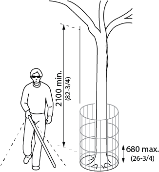
Figure 4.3.14.1 Tree Guard
4.3.14 - Related Sections
4.1.1 Space and Reach Requirements
4.1.2 Ground and Floor Surfaces
4.1.3 Protruding and Overhead Objects
4.1.4 Accessible Routes, Paths and Corridors
4.4.8 Detectable Warning Surfaces
4.4.14 Materials and Finishes
4.4.15 Texture and Colour
4.3.15 - Benches
4.3.15 - Rationale
- Benches provide convenient resting places for all individuals and are especially important for those who may have difficulty with standing or walking for extended periods. Benches should be placed adjacent to pedestrian walkways to provide convenient rest places without becoming potential obstructions. Appropriate seat heights can facilitate sitting and rising for individuals such as senior citizens. Armrests may also provide assistance in sitting and rising. A person with vision loss/no vision may find it easier to locate benches if they are located adjacent to a landmark, such as a large tree, a bend in a pathway, or a sound source.
4.3.15 - Application
- All benches, except those located in unpaved areas of parks, wilderness, beach or unpaved picnic areas, shall be accessible to persons using wheelchairs or other mobility devices.
4.3.15 - Design Requirements
- Benches shall
- be adjacent to an accessible route complying with 4.1.4;
- be stable;
- have a seat height between 450 mm (17-3/4 in.) and 500 mm (19-5/8 in.) from the ground;
- have arm and back rests;
- be of contrasting colour to their background; and
- have an adjacent level, firm ground surface at least 920 mm (36 in.) x 1370 mm (54 in.).
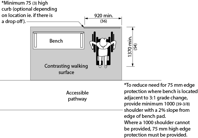
Figure 4.3.15.1 Rest Area
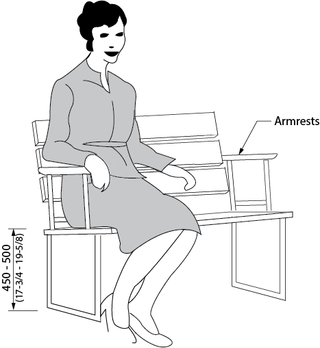
Figure 4.3.15.2 Bench Seating
4.3.15 - Related Sections
4.1.1 Space and Reach Requirements
4.1.2 Ground and Floor Surfaces
4.1.3 Protruding and Overhead Objects
4.1.4 Accessible Routes, Paths and Corridors
4.4.8 Detectable Warning Surfaces
4.4.14 Materials and Finishes
4.4.15 Texture and Colour
4.3.16 - Public Use Eating Areas
4.3.16 - Rationale
- Tables with an extension of the table surface make them accessible to a person using a wheelchair.
- A firm, level surface around the table, with an accessible path leading to the table, is required for wheelchair and scooter accessibility. A change in texture from a pathway to the table area is an important cue for a person with vision loss/no vision.
- Tables that have the support leg(s) in the centre of the table provide a higher level of accessibility.
4.3.16 - Application
- If tables are provided in an accessible public or common use area, at least 20%, but not less than one, for each cluster of tables shall comply with this section. It is preferable to have all tables comply with this section.
- Table seating should provide a variety of locations that allow a choice of view, sun or shade, and protection from outdoor elements such as wind or rain.
- Ensure that chairs with armrests are provided for banquet halls, restaurants and cafeterias.
4.3.16 - Design Requirements
- Tables shall
- have an accessible route leading to the table, and be adjacent to an accessible route complying with 4.1.4;
- have knee space under the table at least 810 mm (32 in.) wide by 480 mm (19 in.) deep and 685 mm (27 in.) high;
- have its top surface located between 810 mm (32 in.) to 865 mm (34 in.) above the finished floor or ground surface;
- be of contrasting colour to their background; and
- have a level, firm ground surface extending min. 2000 mm (78-3/4 in.) on at least two sides of the table for persons who use wheelchairs or scooters and min. 1220 mm (48 in.) on the other sides.
- Illumination is a consideration when positioning outdoor eating areas. Lighting should comply with the requirements of 4.4.13.
- In a retrofit situation where it is technically infeasible to provide the required level surface, the dimensions may be reduced to min. 1220 mm (48 in.) on all sides.
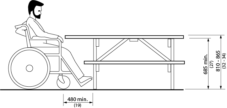
Figure 4.3.16.1 Height and Knee Space at Accessible Tables
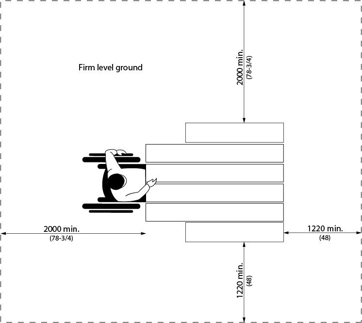
Figure 4.3.16.2 Accessible Tables
4.3.16 - Related Sections
4.1.1 Space and Reach Requirements
4.1.2 Ground and Floor Surfaces
4.1.3 Protruding and Overhead Objects
4.1.4 Accessible Routes, Paths and Corridors
4.4.8 Detectable Warning Surfaces
4.4.13 Lighting
4.4.14 Materials and Finishes
4.4.15 Texture and Colour
4.3.17 - Streetscapes
4.3.17 - Rationale
- Clear paths of travel are important to all individuals using sidewalks and pathways.
- Streetscape elements such as newspaper boxes, trash bins, outdoor patios and bus shelters present a barrier to all pedestrians, especially those that require additional space for use of wheelchairs, scooters, strollers or delivery carts. For persons with a visual impairment, unidentified obstructions within pathways can present a hazard.
- Benches can provide a resting place for an individual with difficulty in walking distances. Such furniture should incorporate strong colour contrasts and be located off pathways, to minimize its potential as an obstruction to pedestrians.
- The efficient and thorough removal of snow and ice are also essential to outdoor pathways.
4.3.17 - Application
- Streetscape elements, including but not limited to, waste receptacles, light standards, signs, planters, mail boxes, vending machines, benches, traffic signals and utility boxes located along sidewalks or paths of travel and contained within the site, shall comply with this section, including streetscape elements that are located inside or outside of facilities.
- All waste receptacles, except those located in unpaved areas of parks, wilderness, beach or unpaved picnic areas or large industrial containers, shall be accessible to persons using wheelchairs or other mobility devices.
4.3.17 - Design Requirements
- Clearances along pedestrian routes must comply with 4.1.3.
- Primary pedestrian routes shall provide a clear and maintained accessible route of at least 2100 mm (82-5/8 in.) wide along the sidewalk.
- Non-primary pedestrian routes, shall provide a clear and maintained accessible route at least 1500 mm (59 in.) wide along the sidewalk.
- The accessible routes along primary pedestrian routes must be identified using a minimum 300 mm (11-3/4 in.) wide continuous contrasting surface along each side of the accessible route. It is preferred that all accessible routes include a minimum 300 mm (11-3/4 in.) indicator surface along each side.
- Streetscape elements shall
- not reduce the required width of the accessible route;
- be cane-detectable, in compliance with 4.1.3;
- be consistently located to one side of the accessible route, entirely within an amenity strip that is hard-surfaced, at least 600 mm (23-5/8 in.) wide, and is identified using a indicator surface;
- be securely mounted within an amenity strip, minimum 600 mm (23-5/8 in.) wide, located adjoining walkways, paths of travel, sidewalks and other accessible routes; and
- incorporate pronounced colour contrast to differentiate it from the surrounding environment.
- Waste receptacles and recycling bins shall be large enough to contain the anticipated amount of waste, so that overflows do not cause a tripping hazard.
- Waste receptacles and recycling bins in accessible open areas, such as parks, wilderness areas, beaches or picnic areas, shall be mounted on firm, level pads adjacent to the path or sidewalk (but not directly beside seating areas).
- Waste receptacles and recycling bins shall be clearly identified by suitable lettering, in compliance with the relevant parts of 4.4.7.
- Where lids or openings are provided on waste receptacles and recycling bins, they shall be mounted no higher than 1060 mm (42 in.) above the adjacent floor or ground surface. Opening mechanisms shall comply with 4.4.2.
- Where mailboxes are provided on a site for facility and/or community access, they shall
- be located immediately adjacent to an accessible route;
- incorporate a clear area at least 760 mm (30 in.) wide x 1370 mm (54 in.) long in front of usable parts;
- where provided, have slots for posting mail located to be reachable from a seated position;
- where provided, have at least 10%, but no less than one, mailbox for collecting mail, located to be reachable from a seated position;
- have operating mechanisms in compliance with 4.4.2; and
- be kept clear of snow.
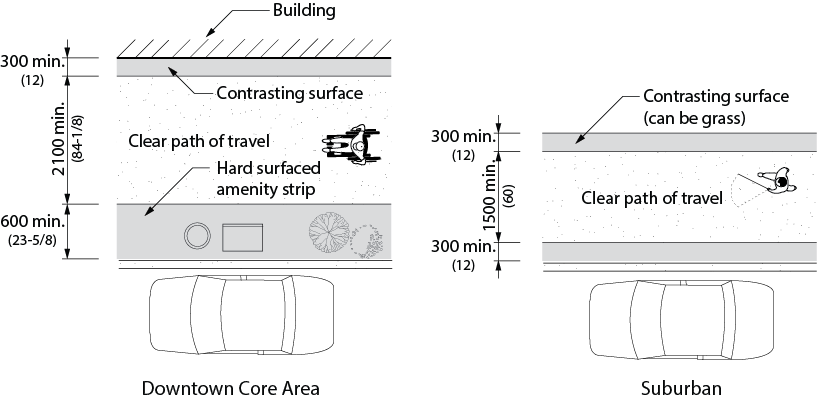
Figure 4.3.17.1 Typical Streetscape Configurations
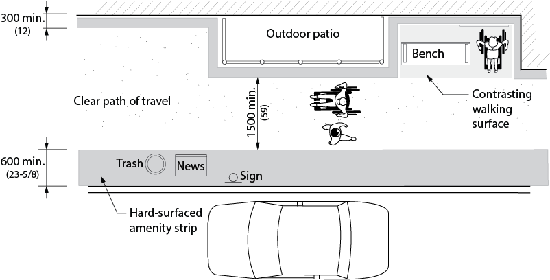
Figure 4.3.17.2 Streetscape
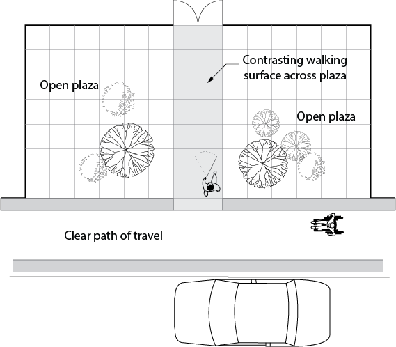
Figure 4.3.17.3 Pathway Across Open Plaza
4.3.17 - Related Sections
4.1.1 Space and Reach Requirements
4.1.2 Ground and Floor Surfaces
4.1.3 Protruding and Overhead Objects
4.1.4 Accessible Routes, Paths and Corridors
4.1.6 Doors
4.1.10 Curb Ramps
4.3.1 Drinking Fountains
4.3.11 Roof-top Patios, Balconies, Porches, Terraces and Patios
4.3.12 Parking
4.3.13 Passenger Loading Zones
4.3.15 Benches
4.3.16 Public Use Eating Areas
4.3.19 Service Animal Relief Areas
4.4.3 Vending and Ticketing Machines
4.4.5 Public Telephones
4.4.7 Signage
4.4.8 Detectable Warning Surfaces
4.4.13 Lighting
4.4.14 Materials and Finishes
4.4.15 Texture and Colour
4.3.18 - Kitchens and Kitchenettes
4.3.18 - Rationale
- Kitchens, kitchenettes and coffee stations require an appropriate level of access to be useable by persons with disabilities. Adequate manoeuvring space is required for users of mobility equipment to approach and use work surfaces, storage elements and appliances. A frontal approach to work surfaces and appliances is generally preferred, except at refrigerators where a side approach is preferred. Where a frontal approach is used, knee space and toe space are required.
- The use of colour contrast between kitchen elements will assist persons with low vision locate surfaces, appliances and controls. Darker coloured work surfaces are preferable as they make it easier to identify objects located on them.
4.3.18 - Application
- Kitchens and kitchenettes intended for use by staff or the public shall comply with this section. Exception: Commercial kitchens.
- At least 50% of shelf space in storage facilities shall comply with this section.
4.3.18 - Design Requirements
- Pass-through kitchens shall have
- where counters, appliances or cabinets are on two opposing sides, or when counters, appliances or cabinets are opposite a parallel wall, clearance between all opposing base cabinets, counter tops, appliances, or walls within a kitchen work area of 1100 mm (43-1/4 in.) minimum; and
- two entries.
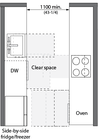
Figure 4.3.18.1 Pass-Through Kitchen
- U-shaped kitchens enclosed on three continuous sides shall have a minimum clearance of 2440 mm (96 in.) between all opposing base cabinets, counter tops, appliances, or walls within kitchen work areas. In a retrofit situation where providing a 2440 mm (96 in.) space is technically infeasible, this space may be reduced to 2130 mm (84 in.).
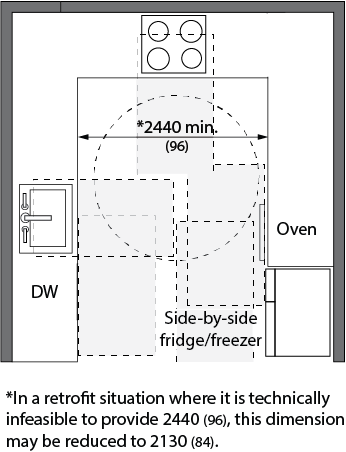
Figure 4.3.18.2 U-Shpaed Kitchen
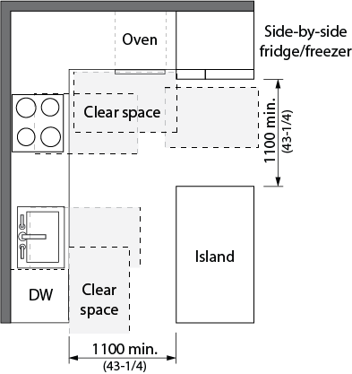
Figure 4.3.18.3 L-Shaped Kitchen with Island
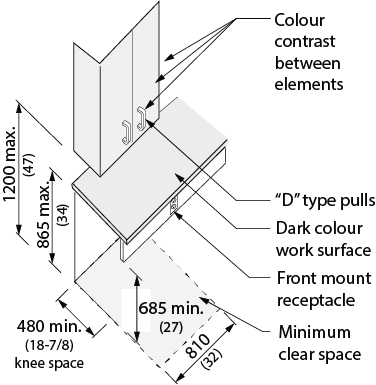
Figure 4.3.18.4 Storage Elements
- Kitchen sinks shall
- be located on an accessible route with adjacent clear floor space for a forward approach. Exceptions: A parallel approach is permitted to a kitchen sink where a cook top or conventional range is not provided and to wet bars;
- where a forward approach is provided, incorporate knee space below at least 810 mm (32 in.) wide, 480 mm (18-7/8 in.) deep, and 685 mm (27 in.) high;
- have the height of the rim or the counter top (whichever is higher) 710–856 mm (28-34 in.);
- incorporate faucets and other controls in compliance with 4.4.2;
- have water supply and drain pipes under the sink insulated or otherwise configured to protect against contact; and
- incorporate no sharp or abrasive surfaces under the sink.
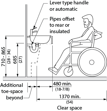
Figure 4.3.18.5 Kitchen Sink
- Kitchen appliances shall
- Dishwashers shall incorporate clear floor space adjacent to the dishwasher door. The dishwasher door, in the open position, shall not obstruct the clear floor space for the dishwasher or the sink.
- Ranges and cooktops shall
- incorporate controls that are located to avoid reaching across the burners; and
- where a forward approach is provided
- incorporate knee space below at least 810 mm (32 in.) wide, 480 mm (18-7/8 in.) deep, and 685 mm (27 in.) high; and
- insulate or otherwise configure the appliance to prevent burns, abrasions, or electrical shock.
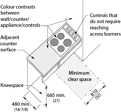
Figure 4.3.18.6 Cook Top
- Ovens shall
- have controls located on the front panels, mounted no higher than 1400 mm (55-1/8 in.);
- where side-hinged doors are used, be located
- with an adjacent work surface positioned adjacent to the latch side of the door; and
- incorporate a pull-out shelf below the oven; and
- where bottom-hinged doors are used, be located with an adjacent work surface positioned adjacent to one side of the door.
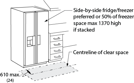
Figure 4.3.18.8 Wall-Mounted Oven
- In facilities with childrens' programs, ranges, cooktops and ovens shall be equipped with a safety switch to de-activate appliance controls.
- Refrigerators/freezers shall
- be configured with at least 50% of the freezer space maximum 1370 mm (54 in.) above the floor; and
- incorporate clear floor space in front, positioned for a parallel approach immediately adjacent to the refrigerator/freezer, with the centre-line of the clear floor space offset 610 mm (24 in.) maximum from the front face of the refrigerator/freezer.
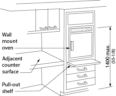
Figure 4.3.18.7 Fridge/Freezer
- Kitchen elements shall incorporate colour contrast to visually differentiate the cabinets and appliances from adjacent wall and floor surfaces, the countertop from the cabinets and adjacent walls, and operable hardware on cabinets.
4.3.18 - Related Sections
4.1.1 Space and Reach Requirements
4.1.2 Ground and Floor Surfaces
4.1.3 Protruding and Overhead Objects
4.1.4 Accessible Routes, Paths and Corridors
4.4.12 Glare and Light Sources
4.4.13 Lighting
4.4.14 Materials and Finishes
4.4.15 Texture and Colour
4.3.19 - Service Animal Relief Areas
4.3.19 - Rationale
- Persons who use a guide dog, who are accompanied by a working companion dog or who utilize other service animals to assist them with mobility, require access to an area for their service animal to relieve themselves. Such service animal relief areas need to be in an accessible location, feature good drainage and provide a garbage can for waste disposal.
4.3.19 - Application
- Service animal relief areas should be provided near large public facilities, such as community centres, arenas, sports fields, parks and outdoor recreation areas, any building where a service animal owner is employed, and in buildings of assembly occupancy which incorporate a meeting space for 50 or more people.
4.3.19 - Design Requirements
- Service animal relief areas shall;
- Be adjacent to an accessible route complying with 4.1.4;
- Be located within 30 metres (98 ft. 5 in.) of an accessible entrance;
- Be an unobstructed, dedicated space at least 1500 x 1500 mm (59 x 59 in.) in size;
- Incorporate a ground surface with drainage (Note: grass is preferable to gravel);
- Incorporate an accessible garbage can;
- Be located away from busy traffic areas such as vehicular access routes and loading docks; and
- Be identified by signage saying “Service Animal Relief Area” complying with 4.4.7.
4.3.19 - Related Sections
4.1.4 Accessible Routes, Paths and Corridors
4.3.17 Streetscapes
4.4.7 Signage
4.4 - Systems and Controls
4.4.1 - Emergency Exits, Fire Evacuation and Areas of Rescue Assistance
4.4.1 - Rationale
- In order to be accessible to all individuals, emergency exits must include the same accessibility features as other doors specified in 4.1.6. The doors and routes must also be marked in a way that is accessible to all individuals, including those who may have difficulty with literacy, such as children or persons speaking a different language. Persons with vision loss/no vision will need a means of quickly locating exits – audio or talking signs could assist. In the event of fire when elevators cannot be used, areas of rescue assistance are an asset to anyone who would have difficulty traversing sets of stairs.
4.4.1 - Application
- In facilities, or portions of facilities, required to be accessible, accessible means of egress shall be provided in the same number as required for exits by the Ontario Building Code.
- Where required exits from a floor level are not accessible, areas of rescue assistance shall be provided on the floor level in a number equal to that of the required exits.
- Every occupiable level in non-residential occupancies above or below the first storey (as defined by the Ontario Building Code) that is accessible, shall
- be served by an elevator that has protection features, as specified in the Ontario Building Code; or
- be divided into at least two zones by fire separations, as specified in the Ontario Building Code.
- In occupiable levels above or below the first storey in residential occupancies, the requirements for a protected elevator or two fire zones may be waived, if an appropriate balcony (as specified in the Ontario Building Code) is provided for each suite.
- Areas of rescue assistance shall comply with this section.
- A horizontal exit meeting the requirements of the Ontario Building Code shall satisfy the requirements for an area of rescue assistance.
4.4.1 - Design Requirements
- Where emergency warning systems are provided, they shall include both audible alarms and visible alarms. Visual alarms shall comply with 4.4.4.
- Accessible means of egress shall comply with 4.1.4.
- Accessible means of egress shall be identified with signage in compliance with the applicable provisions of 4.4.7.
- Optional: Evacuation chairs may be placed at significant areas where applicable.
- Areas of rescue assistance shall
- be located on an accessible route complying with 4.1.4;
- incorporate the number of rescue spaces in accordance with Table 4.4.1;
- be of a size that allows a minimum floor space of 850 mm (33-1/2 in.) x 1370 mm (54 in.) per non-ambulatory occupant;
- be separated from the floor area by a fire separation having a fire-resistance rating at least equal to that required for an exit;
- be served by an exit or firefighters’ elevator;
- be designated as an area of rescue assistance for persons with disabilities on the facility plans and in the facility;
- be smoke protected in facilities of more than three storeys;
- incorporate a 2-way voice communication system for use between each area of rescue assistance and the central alarm and control facility; and
- be identified with signage in compliance with the applicable provisions of 4.4.7, stating AREA OF RESCUE ASSISTANCE and incorprating the international symbol for accessibility for disabled persons.
| Occupant load of the floor area served by the area of rescue assistance | Minimum number of rescue spaces |
|---|---|
| 1 to 400 | 2 |
| Over 400 | 3 plus 1 for each additional increment of 200 persons in excess of 400 persons |
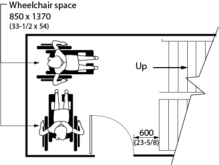
Figure 4.4.1.1 Area of Rescue Assistance
4.4.1 - Related Sections
4.1.1 Space and Reach Requirements
4.1.2 Ground and Floor Surfaces
4.1.3 Protruding and Overhead Objects
4.1.4 Accessible Routes, Paths and Corridors
4.1.6 Doors
4.4.2 Controls and Operating Mechanisms
4.4.4 Visual Alarms
4.4.7 Signage
4.4.8 Detectable Warning Surfaces
4.4.9 Public Address Systems
4.4.14 Materials and Finishes
4.4.15 Texture and Colour
4.4.2 - Controls and Operating Mechanisms
4.4.2 - Rationale
- Operating mechanisms that require a high degree of dexterity or strength will be difficult for many people to use. They can also be obstacles for children, individuals with arthritis or even someone wearing gloves. Controls that require two hands to operate can also be difficult for some people, particularly those with reach or balance limitations, or those who must use their hands to hold canes or crutches.
- The placement of controls is integral to their accessibility. For the individual using a wheelchair, the height of the controls and the space to position the wheelchair in front of the controls are important. Controls placed high on a wall are also difficult for children or persons of short stature.
- Individuals with vision loss/no vision may have difficulty with flush-mounted buttons, touch screens or controls without tactile markings. Controls that contrast in colour from their background, including colour-contrasted raised letters, may be easier to find by an individual with vision loss/no vision. Persons with cognitive challenges may find counterintuitive controls or graphics difficult.
4.4.2 - Application
- Controls and operating mechanisms generally used by staff or public (e.g., light switches and dispenser controls) shall comply with this section. Exception: Restricted-access controls.
4.4.2 - Design Requirements
- A clear, level floor area at least 760 mm x 1370 mm (30 in. x 54 in.) shall be provided at controls and operating mechanisms, such as dispensers and receptacles.
- The operable portions of controls and operating mechanisms such as electrical switches, thermostats and intercom switches, shall be located between 900 mm (35-1/2 in.) and 1100 mm (43-1/4 in.) from the floor. Thermostats and manual pull stations shall be mounted 1200 mm (47-1/4 in.) above the floor. Exceptions: Elevators and power door operator controls - Refer to 4.1.13 and 4.1.6. For card-entry systems an encoded entry/exit systems such as keypads - Refer to 4.4.11.
- Electrical outlets and other types of devices shall be located no lower than 400 mm (15-3/4 in.). Exception: Where electrical outlets are provided as components of systems furniture, these devices need not comply with this section provided they are installed in addition to electrical outlets required by the Authority having Jurisdiction.
- Faucets and other controls shall be hand-operated or electronically controlled.
- Hand-operated controls and mechanisms shall be operable
- with a closed fist;
- without tight grasping, pinching, or twisting of the wrist; and
- with a force of no more than than 22N (5 lb.).
- Controls and operating mechanisms shall be capable of being illuminated to at least a level of 100 lux (9.2 ft-candles).
- Controls and operating mechanisms shall incorporate a pronounced colour contrast, to differentiate them from the surrounding environment.
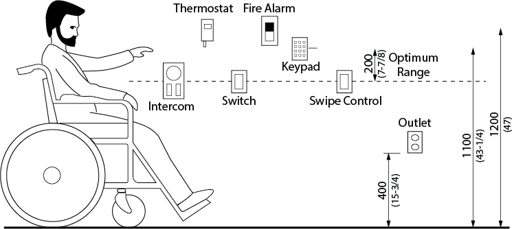
Figure 4.4.2.1 Reach Range for Accessible Controls
4.4.2 - Related Sections
4.1.1 Space and Reach Requirements
4.1.3 Protruding Objects and Overhead
4.1.4 Accessible Routes, Paths and Corridors
4.1.6 Doors
4.1.7 Gates, Turnstiles and Openings
4.1.8 Windows, Glazed Screens and Sidelights
4.1.13 Elevators
4.1.14 Platform Lifts
4.2.2 Toilet Stalls
4.2.3 Toilets
4.2.4 Lavatories
4.2.5 Urinals
4.2.6 Washroom Accessories
4.2.7 Universal Washrooms
4.2.8 Showers
4.3.1 Drinking Fountains
4.3.4 Change/Dressing Rooms
4.3.5 Offices, Work Areas and Meeting Rooms
4.3.9 Storage, Shelving and Display Units
4.3.10 Lockers and Baggage Storage
4.3.17 Streetscapes
4.4.3 Vending and Ticketing Machines
4.4.5 Public Telephones
4.4.10 Information Systems
4.4.11 Card Access, Safety and Security Systems
4.4.13 Lighting
4.4.15 Texture and Colour
4.4.3 - Vending and Ticketing Machines
4.4.3 - Rationale
- Space in front of vending machines allows for manoeuvrability of mobility aids. Seating areas and tables adjacent to vending machines offer convenience and should accommodate the spatial requirements of a wheelchair or scooter. The selection of the machines should include a number of factors. Operating mechanisms should be within reach of children and individuals in wheelchairs. The mechanisms should be operable with one hand and minimal strength, to accommodate a host of disabilities including arthritis, or the need to stabilize oneself with a cane or a handful of bags. Lighting levels and colour contrasts make the machine more accessible to those with vision loss/no vision.
4.4.3 - Application
- Vending and ticketing machines shall comply with this section.
4.4.3 - Design Requirements
- Vending and ticketing machines shall be located on an accessible route in compliance with 4.1.4.
- Clear floor space in front of vending and ticketing machines shall conform to 4.1.1.
- The controls and operating mechanisms on vending and ticketing machines shall comply with 4.4.2.
- Signage on vending and ticketing machines shall be in highly contrasting lettering, at least 13 mm (1/2 in.) high. Ideally, lettering and signage shall comply with relevant parts of 4.4.7.
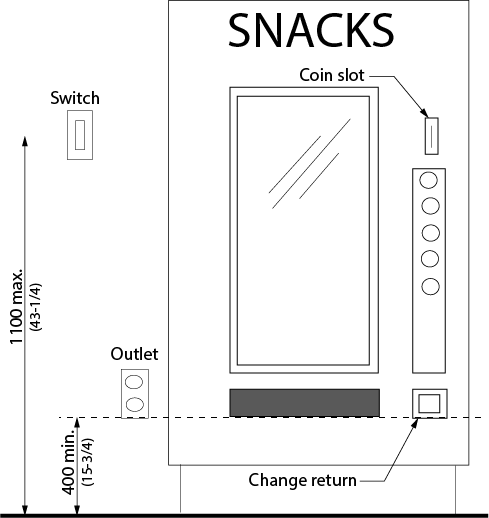
Figure 4.4.3.1 Vending Machine
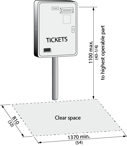
Figure 4.4.3.2 Ticket Dispensing Machine
4.4.3 - Related Sections
4.1.1 Space and Reach Requirements
4.1.4 Accessible Routes, Paths and Corridors
4.4.2 Controls and Operating Mechanisms
4.4.15 Texture and Colour
4.4.4 - Visual Alarms
4.4.4 - Rationale
- Visual alarms are essential safety features for individuals who are deaf, deafened or hard of hearing such that they would not hear an audible alarm.
4.4.4 - Application
- Visual alarms shall comply with this section.
- At a minimum, visual alarm appliances shall be provided in facilities in each of the following areas: restrooms and any other general usage areas (e.g., meeting rooms), hallways, lobbies and any other areas for common use.
- Visual alarm signal appliances shall be integrated into the facility alarm system. If single-station audible alarms are provided, then single-station visual alarms shall be provided.
- A signal intended for the public to indicate the operation of a building security system that controls access to a building shall consist of an audible and visual signal.
4.4.4 - Design Requirements
- Visual alarm signals shall have the following minimum photometric and location features:
- the lamp shall be a Xenon strobe type or equivalent;
- the colour shall be clear or nominal white (i.e. unfiltered or clear filtered white light);
- the maximum pulse duration shall be two-tenths of one second (0.2 sec) with a maximum duty cycle of 40 percent. The pulse duration is defined as the time interval between initial and final points of 10% of maximum signal;
- the intensity shall be a minimum of 75 candela;
- the flash rate shall be a minimum of 1 Hz and a maximum of 3 Hz;
- the appliance shall be placed 2100 mm (82-3/4 in.) above the floor level within the space or 150 mm (5-7/8 in.) below the ceiling, whichever is lower;
- in general, no place in any room or space required to have a visual signal appliance, shall be more than 15 meters (50 ft.) from the signal (in the horizontal plane). In large rooms and spaces exceeding 30 meters (100 ft.) across, without obstructions 2000 mm (78-3/4 in.) above the finished floor, such as auditoriums, devices may be placed around the perimeter, spaced a maximum of 30 meters (100 ft.) apart, in lieu of suspending appliances from the ceiling;
- no place in common corridors or hallways in which visual alarm signalling appliances are required shall be more than 15 m (50 ft.) from the signal; and
- visual component to smoke alarms to conform to the requirements in 18.5.3. (Light, Colour, and Pulse Characteristics) of NFPA 72 “National Fire Alarm and Signalling Code”.
4.4.4 - Related Sections
4.4.1 Emergency Exits, Fire Evacuation and Areas of Rescue Assistance
4.4.5 - Public Telephones
4.4.5 - Rationale
- The placement of telephones should address the limited reach of children or persons in a seated position. Longer cords facilitate the use of the phone for someone unable to get close to the phone due to a mobility device. Adjustable volume controls are important for persons who are hard of hearing, as are shelves that could support a TDD device. A fold-down seat is an asset to someone having difficulty standing for extended periods. Telephones projecting from a wall may present a hazard, particularly to persons with vision loss/no vision, if the sides are not configured to be cane-detectable.
4.4.5 - Application
- Where public pay phones, public closed-circuit phones, or other public telephones are provided, they shall comply with this section to the extent required by Table 4.4.5.
| Number of each type of telephone provided on each floor | Number of accessible telephones required for persons who use wheelchairs or scooters | Number of accessible telephones required for persons who are deaf, deafened or hard of hearing |
|---|---|---|
| 1 or more single units | 1 per floor | 1 per floor |
| 1 bank | 1 per floor | 1 per floor |
| 2 or more banks | 1 per bank (Accessible phones may be installed as single units in proximity to (i.e. either visible or with signage) the bank. At least one public telephone per floor shall meet the requirements for a forward reach telephone. | 1 per bank (Accessible phones may be installed as single units in proximity to (i.e. either visible or with signage) the bank. At least one public telephone per floor shall meet the requirements for a forward reach telephone. |
- All telephones required to be accessible shall be equipped with a volume control. In addition, 25%, but never less than one, of all other public telephones provided shall be equipped with a volume control and shall be dispersed among all types of public telephones, including closed-circuit telephones, throughout the facility.
- Signage complying with applicable provisions of 4.4.7 shall be provided.
- Where an interior public pay telephone is provided, then at least one interior public text telephone (TTY) shall be provided in the facility in a public use area.
- Where an interior public pay telephone is provided in the secured area of a detention or correctional facility, then at least one public text telephone shall also be provided in at least one secured area. Secured areas are those areas used only by detainees or inmates and security personnel.
4.4.5 - Design Requirements
- Accessible telephones shall be on an accessible route complying with 4.1.4.
- Telephones, enclosures and related equipment shall comply with 4.1.3.
- Telephones shall have push-button controls where service for such equipment is available. The characters on the push buttons shall contrast with their background, which should be non-glare (matte finish), and the buttons themselves should contrast with their background.
- The minimum handset cord length of accessible telephones shall be 1000 mm (39-3/8 in.).
- The minimum illumination level at operating mechanisms, the directory, and shelf of accessible telephones shall be 200 lux (18.4 ft-candles).
- Accessible telephones shall
- comply with CSA Standard T515;
- have operable portions within the reach ranges specified in 4.1.1 and the coin slot, located maximum 1100 mm (43-1/4 in.) above the floor;
- have a shelf of at least 350 mm (13-3/4 in.) deep by 500 mm (19-3/4 in.) wide with a minimum 250 mm (9-7/8 in.) clear space above the shelf, to accommodate the use of a portable text telephone;
- have a separate telephone directory shelf (TTY only);
- be equipped with an electrical outlet, within or adjacent to the telephone enclosure (TTY only);
- be equipped with a handset capable of being placed flush on the surface of the shelf (TTY only);
- have a clear floor space of not less than 810 mm (32 in.) wide centred on phone by 1370 mm (54 in.) deep in front of the telephone. NOTE: This space may extend maximum 480 mm (18-7/8 in.) beneath the telephone shelf where knee space clearance of minimum 810 mm (32 in.) wide, 480 mm (18-7/8 in.) deep, and 740 mm (29 in.) is provided; and
- have the top surface of a section of shelf or counter serving at least 1 telephone shall be 775 mm (31 in.) to 865 mm (34 in.).
- Text telephones (TTY’s) used with a pay telephone shall be permanently affixed within, or adjacent to, the telephone enclosure. If an acoustic coupler is used, the telephone cord shall be sufficiently long to allow connection of the text telephone (TTY) and the telephone receiver.
- As new phone technology is developed for persons who are deaf or hard of hearing, installation of these devices should be strongly considered (i.e. video relay).
- Accessible telephones shall be identified by the appropriate symbol of accessibility for mobility impaired persons and/or persons who are deaf or hard of hearing.
- When directional signs for telephones are installed, they shall include the appropriate access symbols.
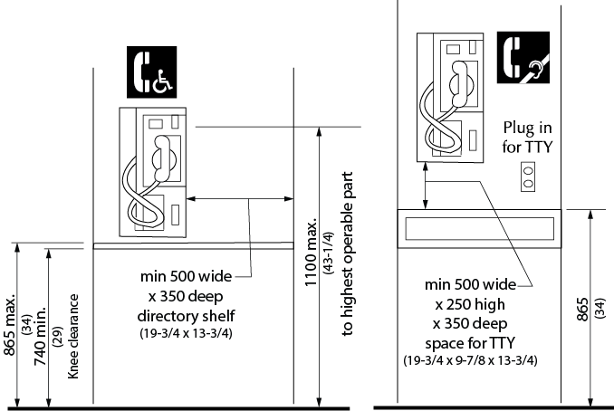
Figure 4.4.5.1-2 Accessible Telephone for Persons who use Wheelchairs or Scooters and Accessible Telephone for Persons who are Deaf, Deafened, Hard of Hearing, or Speech-Impaired.
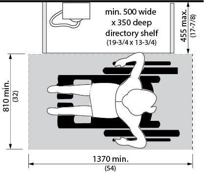
Figure 4.4.5.3 Parallel Approach to a Public Telephone
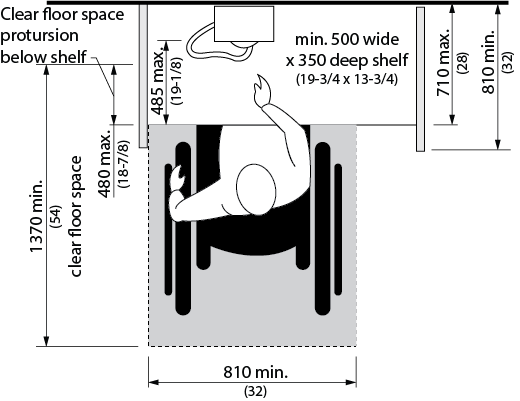
Figure 4.4.5.4 Forward Approach to a Public Telephone
4.4.5 - Related Sections
4.1.1 Space and Reach Requirements
4.1.3 Protruding and Overhead Objects
4.1.4 Accessible Routes, Paths and Corridors
4.4.2 Controls and Operating Mechanisms
4.4.7 Signage
4.4.13 Lighting
4.4.15 Texture and Colour
4.4.6 - Assistive Listening Systems
4.4.6 - Rationale
- The provision of assistive listening devices is important for the range of individuals who may have difficulty hearing.
- Adequate and controllable lighting is required for persons who lip-read, or those who require increased task lighting, due to vision loss/no vision.
4.4.6 - Application
- Assistive listening systems shall comply with this section.
- This section applies to assembly areas where audible communication is integral to the use of the space (e.g., concert theatres, meeting rooms, classrooms, auditoria, etc.). Such assembly areas shall have a permanently installed listening system in compliance with this section where:
- they accommodate at least 50 persons or where they have audio amplification systems or where greater than 100 sq.m. (1080 sq.ft.) in floor area; and
- they have fixed seating.
- For other assembly areas, a permanently installed listening system or an adequate number of electrical outlets or other supplementary wiring necessary to support a portable assistive listening system shall be provided. The minimum number of receivers to be provided shall be equal to 4% of the total number of seats, but no less than two.
4.4.6 - Design Requirements
- Signage complying with applicable provisions of 4.4.7 shall be installed to notify patrons of the availability of a listening system.
- Induction loops, infrared systems and FM radio frequency systems shall be considered acceptable types of assistive listening systems for persons who are hard of hearing.
- Where an induction loop system is installed, dimmer switches and other controls that incorporate transformer coils shall be located so as not to interfere with the audio induction loop.
- Where infrared assistive listening devices are used, overhead incandescent lights shall be located so as not to cancel out the infrared signal at the receiver.
- Where an FM loop system or other assistive listening devices are available in public facilities or meeting areas, portable headsets that are compatible with personal hearing aids shall be made available.
- Where an induction loop system is utilized, at least half the seating area shall be encompassed.
- Where the listening system provided serves individual fixed seats, such seats shall be located within a 15 m (50-ft.) viewing distance of the stage or playing area and shall have a complete view of the stage or playing area.
4.4.6 - Related Sections
4.4.7 - Signage
4.4.7 - Rationale
- Signage should be simple, uncluttered and incorporate plain language. The use of graphic symbols is helpful for individuals such as children; those with a limited literacy level; or those who speak a different language.
- Sharp contrasts in colour make signage easier for anyone to read, particularly someone with vision loss/no vision. The intent of the symbol must be evident, culturally universal and not counterintuitive. To enhance readability, raised tactile lettering should incorporate edges that are slightly smoothed.
4.4.7 - Application
- Signage shall comply with this section.
- Signs that designate permanent rooms or spaces shall be wall-mounted and include tactile characters and numbers. Tactile markings shall also supplement the text of
- regulatory signs, such as prohibition and mandatory signs;
- warning signs, such as caution and danger signs; and
- identification signs, such as rooms, titles, names or numbers.
- Signs that provide direction to, or information about, functional spaces, shall comply with this section. Exception: Facility directories, menus and all other signs that are temporary are not required to comply.
- Elements and spaces of accessible facilities that shall be identified by the International Symbol of Accessibility are
- parking spaces, designated as reserved for individuals with disabilities;
- accessible passenger loading zones;
- accessible ramps located in a barrier-free path of travel serving a building entrance;
- accessible entrances when not all are accessible (inaccessible entrances shall have directional signage to indicate the route to the nearest accessible entrance);
- accessible toilet and bathing facilities, including single-use portable units, when not all are accessible;
- accessible telephones;
- accessible elevators and other elevating devices;
- accessible means of egress; and
- areas of rescue assistance.
- Audible signs (infrared and digital) that are readable by persons with vision loss/no vision using a receiving device may be the sole orientation aid across open spaces. Consideration should be given to including wire drops for future installation.
4.4.7 - Design Requirements
- Letters and numbers on signs shall
- be sans serif (i.e. Helvetica, Univers 55, Verdana, Arial);*
- have Arabic numbers;
- have a width-to-height ratio between 3:5 and 1:1; and
- have a stroke-width-to-height ratio between 1:5 and 1:10.
- Note: Character height dimensions for viewing distance shall comply with Table 4.4.7.
| Minimum character height (mm) | Maximum viewing distance (mm) |
|---|---|
| 200 (7-7/8 in.) | 6000 (19 ft. 8 in.) |
| 150 (5-7/8 in.) | 4600 (15 ft. 0 in.) |
| 100 (3-15/16 in.) | 2500 (8 ft. 2-1/2 in.) |
| 75 (2-15/16 in.) | 2300 (7 ft. 6-1/2 in.) |
| 50 (2 in.) | 1500 (4 ft. 11 in.) |
| 25 (1 in.) | 750 (2 ft. 5-1/2 in.) |
- Signage should use a mix of upper and lower case letters.
- Characters, symbols and backgrounds of signs shall have an eggshell, matte or other glare-free finish.
- Characters and symbols shall have high tonal contrast with their background; either light characters on a dark background or dark characters on a light background.
- Where signs are required to be tactile, letters and numerals shall be
- raised at least 0.8 mm (1/32 in.), not sharply edged;
- be between 16 mm (5/8 in.) and 50 mm (2 in.) high; and
- be sans serif*, accompanied by Grade 2 Braille.

Figure 4.4.7 Sample of Serif and Sans-Serif Fonts
- Pictograms shall be accompanied by an equivalent visual and tactile verbal description, placed directly below the pictogram. The border dimension of the pictogram shall be 150 mm (6 in.) minimum in height.
- Where permanent identification is provided for rooms and spaces, signs shall be installed on the wall adjacent to the latch side of the door, located with their centreline 1370 mm (54 in.) to 1500 mm (59 in.) above the finished floor, with tactile elements located 1200 mm (47-1/4 in.) to 1500 mm (59 in.). Where there is no wall space to the latch side of the door, including at double-leaf doors, signs shall be placed on the nearest adjacent wall.
- The minimum level of illumination on signs shall be 200 lux (18.4 ft-candles).
Figure 4.4.7.1 Colour Contrast on Signs


Figure 4.4.7.2a-e Pictograms (Note: Must incorporate equivalent verbal description.)
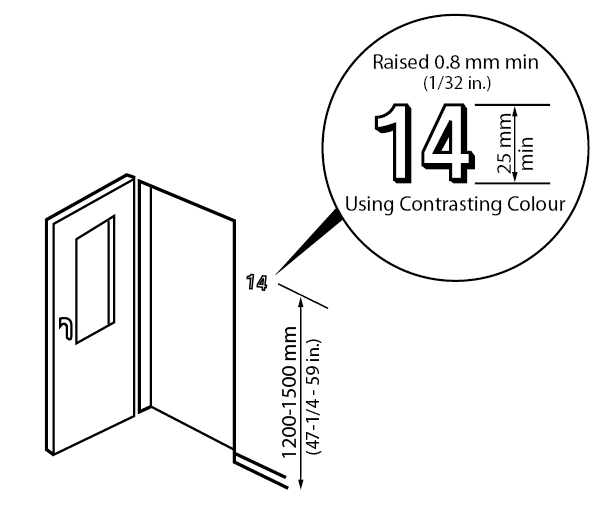
Figure 4.4.7.3 Tactile Lettering
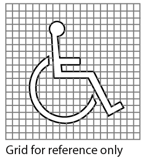
Figure 4.4.7.4 International Symbol of Access
4.4.7 - Related Sections
4.1.3 Protruding and Overhead Objects
4.1.4 Accessible Routes, Paths and Corridors
4.1.5 Entrances
4.1.6 Doors
4.1.7 Gates, Turnstiles and Openings
4.1.9 Ramps
4.1.13 Elevators
4.1.14 Platform Lifts
4.2.1 Toilet Facilities
4.2.7 Universal Washrooms
4.3.2 Viewing Positions
4.3.4 Change/Dressing Rooms
4.3.12 Parking
4.3.13 Passenger-Loading Zones
4.4.1 Emergency Exits, Fire Evacuation and Areas of Rescue Assistance
4.4.5 Public Telephones
4.4.13 Lighting
4.4.15 Texture and Colour
4.4.8 - Detectable Warning Surfaces
4.4.8 - Rationale
- Detectable warning surfaces provide important navigational cues for persons with a visual impairment. These surfaces alert all pedestrians to potential hazards, such as crosswalks or stairs. Suitable surfaces include a change in texture and high colour contrast but should not present a tripping hazard.
- Detectable warning surfaces should be used consistently throughout a facility.
4.4.8 - Application
- Detectable warning surfaces at walkways, curb ramps, stairs, elevated platforms and potential hazards shall comply with this section.
4.4.8 - Design Requirements
- All textured surfaces used as detectable warning surfaces shall be clearly detectable by walking upon as being different from the surrounding surface. (Refer also to 4.4.15). Note: Applying a paint finish to a concrete surface does not provide appropriate detectability.
- Detectable warning surfaces shall contrast visually with adjoining surfaces, being either light on dark or dark on light.
- Detectable warning surfaces shall be slip-resistant.
- Detectable warning surfaces at all stairs shall
- be provided at the top of the stairs and at landings with entry points; and
- extend the full width of the stair for a depth of at least 920 mm (36 in.) commencing one tread depth back from the stair.
- Refer also to section 4.1.11.
- At interior stairs, it is acceptable to provide detectable warning surfaces not more than 3mm above or below adjacent surfaces, however flat-topped domes or cones are preferable.
- Detectable warning surfaces at curb ramps, depressed curbs, exit stairs, exterior stairs and elevated platforms shall be composed of flat-topped domes or cones that
- are 4 - 5 mm (0.16 - 0.20 in.) high;
- have top and bottom dimensions as shown in Table 4.4.8; and
- are arranged in a regular pattern with spacing as shown in Table 4.4.8.
| Top diameter of flat-topped domes or cones | Spacing |
|---|---|
| 12 (0.5) | 42 - 61 (1.7 - 2.4) |
| 15 (0.6) | 45 - 63 (1.8 - 2.5) |
| 18 (0.7) | 48 - 65 (1.9 - 2.6) |
| 20 (0.8) | 50 - 68 (2.0 - 2.7) |
| 25 (1.0) | 55 - 70 (2.2 - 2.8) |
| Bottom diameter of flat-topped domes or cones 10 ± 1 greater than the top diameter. | |
- If a walkway crosses or joins a vehicular way and the walking surfaces are not separated by curbs, railings or other elements between the pedestrian areas and vehicular areas, the boundary between the areas shall be defined by a continuous detectable warning surface, flat-topped domes or cones which is minimum 920 mm (36 in.) wide. Refer also to section 4.1.10.
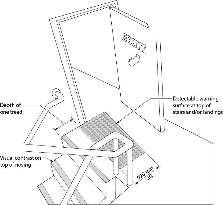
Figure 4.4.8.1 Detectable Warning Surfaces at Stairs
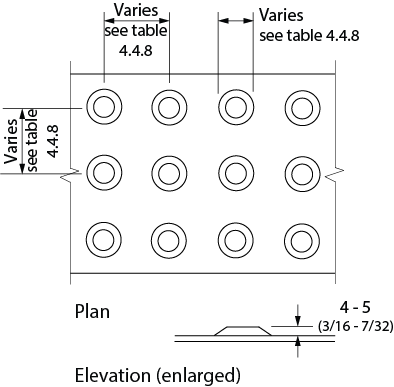
Figure 4.4.8.2 Truncated Dome Detectable Warning Surface
4.4.8 - Related Sections
4.1.3 Protruding and Overhead Objects4.1.4 Accessible Routes, Paths and Corridors
4.1.9 Ramps
4.1.10 Curb Ramps
4.1.11 Stairs
4.1.12 Escalators
4.3.1 Drinking Fountains
4.3.3 Elevated Platforms
4.3.12 Parking
4.3.13 Passenger-Loading Zones
4.4.15 Texture and Colour
Appendix E
4.4.9 - Public Address Systems
4.4.9 - Rationale
- Public address systems should be designed to best accommodate all users, especially those that may be hard of hearing. They should be easy to hear above the ambient background noise of the environment and there should be no distortion or feedback. Background noise should be minimized.
- Visual equivalents should be made available for individuals with hearing loss/persons who are hard-of-hearing who may not hear an audible public address system.
4.4.9 - Application
- Public address systems shall comply with this section.
4.4.9 - Design Requirements
- Public address speakers shall be mounted above head level, and provide effective sound coverage in required areas, such as corridors, assembly and meeting room areas, recreational and entertainment facilities, educational facilities, and common use areas in institutional settings.
- Public address systems shall be zoned so that information can be directed to key locations only, minimizing background noise in other areas.
- Where public address systems are used to broadcast background music, the music shall not be broadcast continuously or throughout the entire facility.
- All-point call systems shall only be utilized for fire and emergency information.
- Paging systems for staff and other key persons shall be discreet and low volume, and sound only at those devices or locations where such persons might expect to be located.
4.4.9 - Related Sections
4.4.1 Emergency Exits, Fire Evacuation and Areas of Rescue Assistance
4.4.16 Acoustics
4.4.10 - Information Systems
4.4.10 - Rationale
- Information should be accessible to all facility users. Where universally accessible formats are technically not feasible, alternate formats should be available. Video display terminals may present particular difficulties for persons with vision loss. Alternate technology or audio interfaces are required. To ensure that a person using a wheelchair can access an information terminal, consideration should be given to the lower vantage point and reach ranges of all information systems provided.
4.4.10 - Application
- Information systems, such as display kiosks, video display terminals, parks and recreational trails mapping, and interpretive/informational panels shall comply with this section.
4.4.10 - Design Requirements
- Where information is provided by video display terminals to the general public, clients or customers, the same information shall be provided in an alternative format, such as audio, Braille and large-text print. The minimum font size for large-text print shall be 16 point. Refer to the Canadian National Institute of the Blind "Clear Print Guidelines" for further detail.
- Information systems designed for direct access by the public, such as touch-screen video display, keyboard or keypad access, shall be mounted at a height suitable for use by a person using a wheelchair or scooter (Refer to 4.4.2).
- Essential print information shall be printed in large text on a highly contrasting background colour, and should also be available in other formats, such as audiotape.
- Push buttons or other controls for accessing public information systems should be clearly identifiable by colour and/or tone from the background colour, and should include raised numbers, numerals or symbols for easy identification by persons with a low or no vision.
- Tactile identification shall comply with 4.4.15.
- Exhibits that include important artefacts, labels and graphics, shall be placed 1000 - 1200 mm (39-3/8 - 47 in.) from the floor.
- Labels and descriptive signage shall be inclined from horizontal for easier reading.
- Inclined informational/interpretive panels that can not be read from 750 mm (30 in.) away shall have at least 660 mm (26 in.) of knee clearance and at least 470 mm (18 in.) depth. If displays are intended for viewing from 750 mm (30 in.) or further, less clearance is permitted to a minimum height of 220 mm (9 in.) for toe kick clearance. The top of the panel shall be not more than 1220 mm - 1380 mm (48 in. - 54 in.) high.
- Vertical informational/interpretive panels shall have text located no higher than 1750 mm (69 in.). Text shall not be lower than 750 mm (29-1/2 in.) above the floor.
- No part of the sign shall encroach on the path of travel. If encroachment is unavoidable, cane-detection through colour and texture change shall be provided on the ground.
- A minimum 1500 mm x 1500 mm (60 in. x 60 in.) clear space directly in front of the sign as well as the clearances needed around such, is required for it's approach and use. The clear space must be of a hard surface material.
- Automated banking machines shall comply with Canadian Standards Association B651.1 Barrier-Free Design for Automated Banking Machines (latest edition).
- Self-service interactive devices shall comply with Canadian Standards Association B651.2 Accessible Design for Self-Service Interactive Devices (latest edition).
- Signage and other media for recreational trails and footbridges shall conform with 4.5.2.
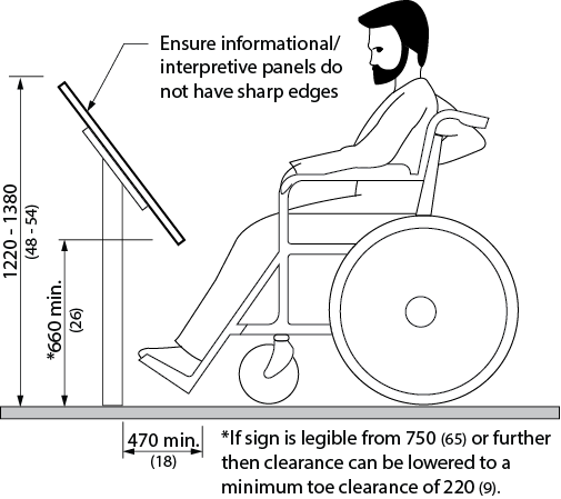
Figure 4.4.10.1 Critical Dimensions for Information Systems and Displays
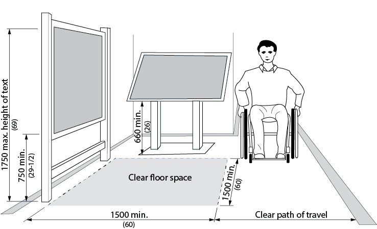
Figure 4.4.10.2 Clear Space and Dimensions around Information Systems
4.4.10 - Related Sections
4.4.2 Controls and Operating Mechanisms
4.4.15 Texture and Colour
4.4.11 - Card Access, Safety and Security Systems
4.4.11 - Rationale
- In many cases, persons such as seniors and persons with disabilities may be considered to have a higher degree of vulnerability and therefore seek more reassurance and inherent security. Items such as adequate lighting and accessible signalling devices promote this security.
- Emergency signalling devices are important in individual washrooms where the potential for a fall is increased and an individual may be alone.
- Where card-access systems are selected as a means of entry to particular facilities or spaces, the systems and components selected should be suitable for use by persons with varying abilities, including persons with reduced manual dexterity, poor vision or difficulty with reaching.
4.4.11 - Application
- Card-access, safety and security systems shall comply with this section.
- Where signals intended for the public to indicate the operation of a building security system are provided, they shall consist of both audible alarms and visual signals.
4.4.11 - Design Requirements
- Adequate lighting shall be provided continuously along public walkways, steps and ramps that are actively used at all times of year and/or where staff and public parking is provided.
- Where public telephones are installed, an accessible public telephone complying with 4.4.5 shall be located at, or close to an accessible entrance, for the use of persons requiring assistance.
- Where accessible universal washrooms in compliance with 4.2.7 are provided in larger public facilities, such as recreation facilities, the washroom shall incorporate an emergency call system linked to a central location (e.g., office or switchboard).
- Card-entry systems shall
- be wall-mounted, no higher than 1060 mm (42 in.) above the floor or ground, adjacent to the door and free of the door swing;
- be colour-contrasted from the surface on which they are mounted;
- incorporate a card slot that is illuminated or colour contrasted from the mounting plate; and
- use cards that incorporate a distinctive colour, texture or raised graphic/lettering on one side.
- Encoded-entry/exit systems, such as keypads, shall
- be wall-mounted, between 900 mm (35-1/2 in.) and 1200 mm (47 in.) above the floor or ground. It is preferred to install keypads at 1100mm (43-1/4 in.) from the floor on an adjustable mounting surface;
- be mounted adjacent to the door and free of the door swing; and
- incorporate buttons that
- are raised;
- are mounted on a clearly differentiated coloured background; and
- include raised numerals or letters in a constant array.
4.4.11 - Related Sections
4.1.1 Space and Reach Requirements
4.1.4 Accessible Routes, Paths and Corridors
4.1.5 Entrances
4.1.6 Doors
4.1.13 Elevators
4.1.14 Platform Lifts
4.2.7 Universal Washrooms
4.3.5 Offices, Work Areas and Meeting Rooms
4.4.2 Controls and Operating Mechanisms
4.4.13 Lighting
4.4.15 Texture and Colour
4.4.12 - Glare and Light Sources
4.4.12 - Rationale
- Direct or reflected glare from floors, walls or work surfaces is uncomfortable for all users and a barrier to persons with reduced vision. Therefore, every attempt should be made to select light sources, materials and finishes which do not add to the problem, and to ensure that natural daylight is controllable.
- The strategic use of lighting is valuable to all individuals, and especially important for individuals with some form of vision loss/no vision. In addition, offering a variety of task lighting at work areas is beneficial to all.
4.4.12 - Application
- Systems used to control glare and excessive reflected light shall comply with this section.
4.4.12 - Design Requirements
- Extensive high gloss floor and wall finishes are not acceptable, but high-gloss materials may be incorporated into floor and wall finish details, as long as they do not result in large reflective surfaces.
- Monolithic floor surfaces, such as stone, granite, marble or terrazzo, shall have a matte or honed finish, to minimize reflected glare.
- Finishes such as vinyl, other composition materials, quarry tile, glazed tile or mosaics, used on horizontal surfaces, such as floors and work surfaces, shall be in matte or satin finishes.
- Finishes such as paint, vinyl wall coverings, stone, marble, wood, metals, plastic laminate, etc., used on vertical surfaces, such as walls and columns, shall have matte or satin finishes.
- Curtains, blinds or other sun-screening systems shall be provided at windows and other places where direct sunlight can adversely affect the level of lighting and/or reflected glare.
- Light fixtures shall be selected with diffusers, lenses or recessed light sources, so that no glare is created.
- Where surface-mounted fluorescent ceiling fixtures are mounted below 2440 mm (96 in.), they shall have darkened sides (i.e., not wrap-around lenses) and be positioned perpendicular to the dominant direction of travel, or used in valance-type lighting along the perimeter of a space, resulting in indirect lighting.
- The location of special features and key orientation elements shall be enhanced through the use of supplementary lighting. Such lighting shall have upward or downward components only.
4.4.12 - Related Sections
4.1.2 Ground and Floor Surfaces
4.1.4 Accessible Routes, Paths and Corridors
4.1.5 Entrances
4.1.8 Windows, Glazed Screens and Sidelights
4.1.9 Ramps
4.1.10 Curb Ramps
4.1.11 Stairs
4.1.13 Elevators
4.1.14 Platform Lifts
4.2.1 Toilet Facilities
4.3.8 Information, Reception and Service Counters
4.4.13 Lighting
4.4.13 - Lighting
4.4.13 - Rationale
- Artificial lighting and natural light sources should provide comfortable, evenly distributed light at all working areas, in all circulation routes and in all areas of potential hazard. Also, outdoor lighting should be provided at entrances, along frequently used access routes and at frequently used outdoor amenities.
4.4.13 - Application
- Exterior and interior lighting systems shall comply with this section.
4.4.13 - Design Requirements
Exterior Lighting
- Exterior lighting shall be in compliance with Illuminating Engineering Society of North America Standards in all public thoroughfares, and at all pedestrian routes, to provide safe access for persons with disabilities from sidewalks, bus stops and parking areas to nearby facilities and site amenities.
- At pedestrian entrances, lighting levels should be minimum 100 lux (9.4 ft-candles) consistently over the entrance area, measured at the ground.
- Over frequently used pedestrian routes, including walkways, paths of travel, stairs and ramps, lighting levels shall be 50 lux (5 ft-candles) Extended avg., 40 lux (4 ft-candles) avg./min., 20 lux (2 ft-candles) min. maintained consistently over the route, measured at the ground. For mixed pedestrian/cycling routes: 20 lux (2 ft-candles) Extended avg., 40 lux (4 ft-candles) avg./min., 10 lux (1 ft-candle) min. maintained.
- At designated parking spaces including accessible spaces and limited mobility/caregivers spaces, lighting levels shall be minimum 30 lux (3 ft-candles) consistently over each of these parking spaces, measured at the ground.
- Lighting levels at passenger drop-off areas shall be minimum 30 lux (3 ft-candles) consistently over the drop-off area, measured at the ground.
- At frequently used steps and stairs, lighting shall be located at or beside the steps or stairs, to clearly define the treads, risers and nosings.
- All lighting shall
- provide a good colour spectrum; and
- be evenly distributed to minimize cast shadows.
- Supplementary lighting shall be provided to highlight key signage and orientation landmarks.
- Low/ground-level lighting (such as bollards) shall be high enough to clear normal snow accumulation.
- Lighting fixtures shall comply with the relevant parts of 4.1.3 and 4.3.17.
Interior Lighting
- Light sources and fixtures shall be selected to minimize direct glare or indirect glare on nearby reflective surfaces.
- Light sources shall provide as full a spectrum of light as possible, as an aid to edge and colour definition.
- Lighting shall be configured to create an even distribution at floor level and to minimize pools of light and areas of shadow.
- The leading edge of stairs, steps, ramps or escalators shall be evenly lit to minimize tripping hazards.
- Lighting levels in elevator lobbies shall be similar to the lighting levels in elevator cabs, to minimize tripping hazards, and in no case shall be less than 200 lux (20 ft-candles).
- Lighting levels in washrooms and dressing rooms shall be evenly distributed and no less than 200 lux (20 ft-candles).
- Lighting levels in office areas shall be evenly distributed and no less than 300 lux (30 ft-candles).
- Emergency lighting over stairs and ramps, in an exit or path of travel, shall be at least 100 lux (10 ft-candles), generally at the walking surface, and in no place less than 50 lux (5 ft-candles).
- Lighting over directional or informational signage, or highlighting other orientation features, at public telephones, information or service counters, and card or keypad security systems, shall be no less than 200 lux (20 ft-candles) measured at the working surface.
- Lighting in meeting rooms and assembly areas shall be evenly distributed, and shall be capable of being adjusted (e.g., dimmers).
- Lighting at lecterns, podiums/platforms or other speaker locations shall be capable of being enhanced, even when other lighting is dimmed, to permit ease of lip-reading and/or viewing of the hand actions of a nearby ASL translator for persons who are deaf.
4.4.13 - Related Sections
4.1.3 Protruding and Overhead Objects
4.1.4 Accessible Routes, Paths and Corridors
4.1.5 Entrances
4.1.9 Ramps
4.1.10 Curb Ramps
4.1.11 Stairs
4.1.13 Elevators
4.1.14 Platform Lifts
4.2.1 Toilet Facilities
4.3.1 Drinking Fountains
4.3.3 Elevated Platforms
4.3.4 Change/Dressing Rooms
4.3.5 Office, Work Areas and Meeting Rooms
4.3.8 Information, Reception and Service Counters
4.3.17 Streetscapes
4.4.2 Controls and Operating Mechanisms
4.4.5 Public Telephones
4.4.7 Signage
4.4.12 Glare and Light Sources
4.4.14 - Materials and Finishes
4.4.14 - Rationale
- The selection of flooring materials can be critical to the safe and easy movement of persons using all kinds of mobility aids, as well as persons with low vision.
- Floor finishes, such as carpet, should be selected and installed so that persons using wheelchairs and walkers or other mobility aids can easily travel over them without using undue energy or tripping.
- Finishes that are slip-resistant and not highly reflective promote safe travel.
4.4.14 - Application
- Exterior and interior materials and finishes shall comply with this section.
4.4.14 - Design Requirements
Exterior Finish Materials
- Suitable materials for exterior route of travel should be firm and stable and may include materials such as:, concrete, asphalt, precast paving or unit paving, interlocking brick and patio stones or decking. Other surfaces may be suitable as new innovative materials become available. Where wooden planks are used for boardwalks, they shall be laid perpendicular to the path of travel. Such materials shall
- have joints that are no greater than 6 mm (1/4 in.) wide, with variations in level of no more than 3 mm (1/8 in); and
- be laid to drain.
- Where possible, gratings and grills shall be located to one side of the pedestrian walkways, so as not to impede the accessible route. Where this is not possible, the bars of the grating or grill shall be located perpendicular to the dominant path of travel, with openings of no greater than 13 mm (1/2 in.).
- Steps shall be finished with a non-slip material and incorporate highly contrasted nosings.
- Ramp surfaces shall be firm and non-slip.
- Handrails and guards shall be continuous, smooth and well maintained.
Interior Materials and Finishes
- Carpet shall be of low-level loop construction, 10 or 12-gauge non-static fibre, directly glued to the subfloor.
- Where hard, monolithic materials are selected, they shall be non-slip and non-glare, complying with 4.4.12.
- Where floor tiles, bricks or pavers are used, joints should be no wider than 6 mm (1/4 in.) and should be flush.
- Wall surfaces in corridors shall be non-abrasive from the floor level to a minimum of 2000 mm (78-3/4 in.) above the finished floor.
4.4.14 - Related Sections
4.1.2 Ground and Floor Surfaces
4.1.4 Accessible Routes, Paths and Corridors
4.1.5 Entrances
4.1.9 Ramps
4.1.10 Curb Ramps
4.1.11 Stairs
4.1.13 Elevators
4.1.14 Platform Lifts
4.2.1 Toilet Facilities
4.3.4 Change/Dressing Rooms
4.3.5 Office, Work Areas and Meeting Rooms
4.4.12 Glare and Light Sources
4.4.15 - Texture and Colour
4.4.15 - Rationale
- The ability of an individual with vision loss/no vision to navigate an environment can be enhanced through the strategic use of colour and texture.
- Caution is recommended in the selection of heavy or distinct patterns on walls or floors, since these can add visual confusion to settings for persons with low vision. Simple, repetitive, non-directional patterns that feature monochromatic or low-colour contrast are preferred. Changes in material or texture should not necessitate a threshold.
4.4.15 - Application
- Textural and colour systems shall be used to enhance accessibility and shall comply with this section.
4.4.15 - Design Requirements
- Exterior colour schemes shall incorporate a pronounced colour contrast, to differentiate boundaries of objects, distinguish objects from their background, and to generally enhance spatial orientation. Generally, for seniors and persons with low vision, colours in the warm end of the spectrum (yellow, orange, bright red, etc.) are easier to recognize than those at the cool end of the spectrum.
- Signs shall incorporate pronounced glare-free colour contrast. A minimum contrast of 70% light reflectance is required. For signs, the most visible colours are white or yellow on a black, charcoal or other dark background, such as brown, dark blue, dark green or purple. Black lettering on white is also acceptable, although less readable than the reverse. Signage should avoid using the colour combinations yellow/grey, yellow/white, blue/green, red/green, black/violet, or red/black, since these combinations are unreadable for people with various visual conditions (i.e. colour blindness.)
- Colour contrast shall be used as a safety measure to define edges or boundaries of objects (e.g., stair nosings, doors, handrails, etc.). Colour or tone shall be used to visually define the boundaries of a room (i.e., where the wall meets the floor). Baseboards in monochromatic environments shall be highly contrasting with the wall and floor colours, to provide boundary definition.
- Colour shall be used consistently to visually identify distinctive objects (e.g., exit doors).
- Bright colours and/or a highly contrasting tone shall be used to assist with wayfinding. (e.g. If used as part of a signage band located on walls at eye level, this band is easier to follow than monolithic wall colouring, and can be the visual cue for other essential signs.)
- End walls or return walls in long corridors shall be visually defined using highly contrasting colours or tone, to enhance a change of direction or the end of the space.
- Detectable warning surfaces shall be used to define potential hazards. (Refer to 4.4.8.). All textured surfaces used as detectable warning surfaces shall be clearly detectable by walking upon as being different from the surrounding surface.
- Supplementary textural cues shall also be provided (e.g., by using different floor textures or materials, in major and minor routes).
- Clearly defined boundaries of materials like carpeting or floor tiles shall enhance wayfinding by defining such as the junction between walls and floors, doorway recesses and corridor intersections.
- The same texture shall be used consistently throughout any one site to identify the same type of hazard.
4.4.15 - Related Sections
4.1.2 Ground and Floor Surfaces
4.1.4 Accessible Routes, Paths and Corridors
4.1.6 Doors
4.1.7 Gates, Turnstiles and Openings
4.1.8 Windows, Glazed Screens and Sidelights
4.1.9 Ramps
4.1.10 Curb Ramps
4.1.11 Stairs
4.1.12 Handrails
4.1.13 Elevators
4.1.14 Platform Lifts
4.2.2 Toilet Stalls
4.2.3 Toilets
4.2.4 Lavatories
4.2.5 Urinals
4.2.6 Washroom Accessories
4.2.7 Universal Washrooms
4.2.8 Showers
4.2.9 Grab Bars
4.3.1 Drinking Fountains
4.3.3 Elevated Platforms
4.3.4 Change/Dressing Rooms
4.3.5 Office, Work Areas and Meeting Rooms
4.3.6 Waiting and Queuing Areas
4.3.8 Information, Reception and Service Counters
4.3.9 Storage, Shelving and Display Units
4.3.10 Lockers and Baggage Storage
4.3.11 Roof-top Patios, Balconies, Porches, Terraces and Patios
4.3.14 Landscaping Materials and Plantings
4.3.15 Benches
4.3.16 Public Use Eating Areas
4.3.17 Streetscapes
4.4.1 Emergency Exits, Fire Evacuation and Areas of Rescue Assistance
4.4.2 Controls and Operating Mechanisms
4.4.5 Public Telephones
4.4.7 Signage
4.4.8 Detectable Warning Surfaces
4.4.11 Card Access, Safety and Security Systems
4.4.16 - Acoustics
4.4.16 - Rationale
- The acoustic environment of public buildings and spaces should accommodate the unique needs of persons who are hard of hearing and who need to differentiate essential sounds from general background noise. The sound transmissions of different areas can be used as an orientation cue and help to navigate a space. A well designed acoustical environment is to everyone's advantage.
4.4.16 - Application
- The acoustical environment of facilities used by the general public, clients, customers and employees shall comply with this section.
4.4.16 - Design Requirements
- Floor finishes, wall surfaces and ceilings shall be selected so that occasional noise is not unduly amplified. (e.g., Hard surfaces such as marble or terrazzo will allow each foot step to be heard by persons with low/no vision, but add another level of confusion for persons with hearing loss.)
- At accessible routes in large facilities where wayfinding is problematic, the sound transmission/reflection characteristics of finish materials shall aurally differentiate major and secondary paths of travel.
- Ceiling shapes shall be designed so that echoes do not occur, unless an alternate acoustical treatment is incorporated. (Note: Domed shapes tend to distort sound.)
- Public address and call systems shall be capable of being zoned to key areas, rather than blanketing all areas of a facility at all times. (Refer to 4.4.9.)
- In meeting rooms and assembly areas where the spoken word is key to comprehending the proceedings, all unnecessary background noise (e.g., from fans or other mechanical equipment, air diffusers, etc.) shall be dampened and/or the room shall include adequate sound insulation.
4.4.16 - Related Sections
4.3.5 Office, Work Areas and Meeting Rooms
4.3.8 Information, Reception and Service Counters
4.4.5 Public Telephones
4.4.6 Assistive Listening Systems
4.4.9 Public Address Systems
4.4.17 - Pedestrian Signals
4.4.17 - Rationale
- Pedestrian crossovers should be designed to accommodate all users equally. The physical location of the controls can help identify specific directional paths, and auditory signals will enable user with low vision to locate the controls quickly.
4.4.17 - Application
- Where new pedestrian signals are being installed or existing pedestrian signals are being replaced at a pedestrian crossover, they must be accessible pedestrian signals.
4.4.17 - Design Requirements
- Accessible pedestrian signals must;
- have a locator tone that is distinct from a walk indicator tone;
- be installed within 1500 mm (59 in.) of the edge of the curb;
- be mounted at a maximum of 1100 mm (43-1/4 in.) above ground level;
- have tactile arrows that align with the direction of crossing;
- include both manual and automatic activation features; and
- include both audible and vibro-tactile walk indicators.
- Where two accessible pedestrian signal assemblies are installed on the same corner, they must be a minimum of 3000mm (118 in.) apart.
- Where the accessible pedestrian signal cannot meet the 3000 mm (118 in.) minimum requirement due to site constraints or existing infrastructure, two accessible pedestrian signal assemblies can be installed on a single post, and when this occurs, a verbal announcement must clearly state which crossing is active
- In this section, "pedestrian crossover' means a pedestrian crossover as defined in subsection 1 (1) of the Highway Traffic Act.
4.4.17 - Related Sections
4.1.4 Accessible Routes, Paths, And Corridors
4.4.2 Controls and Operating Mechanisms
4.5 - Facility-Specific Requirements
4.5.1 - Arenas, Halls and Other Indoor Recreational Facilities
4.5.1 - Rationale
- Opportunities for recreation, leisure and active sport participation should be available to all members of the community. Access should be provided to halls, arenas, and other sports facilities, including access to the site, all activity spaces, gymnasia, fitness facilities, lockers, change rooms and showers. Persons with a disability may be active participants, as well as spectators, volunteers and members of staff.
- For waiting areas in these facilities, the provision of benches is important for individuals who may have difficulty with standing for extended periods.
4.5.1 - Application
- In addition to the design requirements specified in 4.1 to 4.4, arenas, halls and other indoor recreation facilities shall comply with this section.
4.5.1 - Design Requirements
- Arenas, halls and other indoor recreation facilities shall
- where visitor, spectator and/or participant seating is provided,
- provide an accessible route in compliance with 4.1.4 to the arena/facility floor and/or ice surface, including access panels or gates providing at least 950 mm (37-1/2 in.) clear width;
- where facilities are provided for performances and other events, have a direct accessible route in compliance with 4.1.4 from the lobby/entrances and viewing locations to all performing areas, including stages, dressing rooms, washrooms and all other spaces used by performers;
- where stairs are provided, have stairs that comply with 4.1.11, including appropriate tactile and colour-contrasting features;
- where dressing facilities are provided, have dressing facilities that comply with 4.3.4;
- where lockers or shelving is provided, have lockers and shelving that comply with 4.3.9 and 4.3.10;
- where coat hooks are provided, have at least 10%, but never less than one, within the reach ranges specified in 4.1.1;
- where toilets and bathing facilities are provided, have toilets and bathing facilities that comply with 4.2.1;
- where concessions or other service counters are provided, comply with 4.1.3 and 4.3.8;
- where swimming pool, hot pools or therapy pools are provided, comply with 4.5.3; and
- where staff accommodation and related support areas, offices or meeting rooms are provided, comply with all relevant sections of 4.1 to 4.4.
- To allow for Sledge Hockey in arenas, construct accessible players boxes where the boards can be removed and clear Plexiglas is used with low thresholds. Refer to the CRFC (Canadian Recreation Facilities Council) Sledge Hockey Accessibility Design Guidelines for Arenas.
4.5.1 - Related Sections
All relevant parts of Sections 4.1, 4.2, 4.3 and 4.4.
4.5.2 - Outdoor Recreational Facilities
4.5.2 - Rationale
- Opportunities for recreation, leisure and active sport participation should be available to all members of the community. Access should be provided to playing fields and other sports facilities, including access to the site, all activity areas, outdoor recreational trails, docks, swimming areas, play spaces, lockers, change rooms and showers. Persons with a disability may be active participants, as well as spectators, volunteers and members of staff.
4.5.2 - Application
- In addition to the design requirements specified in 4.1 to 4.4, the outdoor recreation facilities listed below shall comply with this section.
- Where dressing facilities are provided, they shall comply with 4.3.4.
4.5.2 - Design Requirements
General
- Parks accessibility shall encompass the development of routes, auxiliary services, planting and an overall environment which is accessible and provides a fulfilling recreational experience for all persons with a varying level of ability.
Boardwalks
- Where boardwalks are provided, they shall
- have a minimum width of 2000 mm (78-3/4 in.);
- incorporate surfaces constructed of firm, stable, non-slip materials and comply with 4.4.14;
- not have any surfaces that allow the passage of an object that has a diameter of more than 20 mm (3/4 in.);
- incorporate a continuous curbed edge where the grade drop-off on any side of the boardwalk is greater than 200 mm (7-7/8 in.). The curbed edge shall be at least 75 mm (3 in.) high and of a contrasting colour to the surrounding terrain (if the curb edge cannot be provided, a protective barrier must be provided with a maximum height of 1070 mm (42-1/8 in.);
- handrails, guards or other suitable barriers must be provided where the grade drop-off is greater than 450 mm (17-3/4 in.);
- access points to boardwalks that allow easy wheelchair access; and
- benches, garbage cans, drinking fountains, etc., where provided, shall be located adjacent to the boardwalk on firm, level surfaces at the same elevation as the boardwalk. (Refer also to 4.3.17.)
Docks/Piers
- Where docks for fishing, boating, water-taxi or swimming are provided they shall:
- be located on an accessible route in compliance with Section 4.1.4;
- incorporate firm and stable surfaces at transition points (such as from a walkway to a dock, or between adjacent dock units);
- incorporate clearly painted markings at transition points;
- where changes in elevation are necessary, incorporate ramps or curb ramps in compliance with Sections 4.1.9 Ramps and 4.1.10 Curb Ramps. Ramps with a slope no greater than 1:20 (8.3%) at low water are acceptable;
- be no higher than 600 mm (23-3/4 in.) above the water;
- incorporate a continuous curbed edge, at least 75 mm (3 in.) high and of a contrasting colour where dock surfaces are greater than 200 mm (7-7/8 in.) above the surface of the water;
Exception to edge protection: Where boat loading openings are provided; incorporate a guard where dock surfaces are greater than 450 mm (17-3/4 in.) above the surface of the water. - where steps are provided to access the water for swimming, incorporate colour-contrasting handrails at the steps. Such handrails shall extend to a minimum of 600 mm (23-5/8 in.) above the dock surface and return down to the dock.
Outdoor Pools
- Outdoor swimming pools shall comply with 4.5.3.
Recreational Trails and Footbridges
- Entrances to recreational trails to have a clear opening between 850 - 1000 mm (33-1/2 - 39-3/8 in.)
- Trail width shall be at least 1000 mm (39-3/8 in.).
- Where significant changes in grade occur, recreational trail routes shall ideally be sloped at no greater than 1:20, or have adjacent steps and ramps. Where this is not possible due to site constraints, a 1:10 slope is acceptable. If greater than 10% consult with the AAC.
- Trail surfaces shall be firm and stable.
- Where steps, footbridges or ramps are used, the surfacing shall be of non-slip materials and include suitable colour-contrasting handrails and/or guards.
- The slope on foot bridges shall not exceed 1:10.
- Ramps shall conform with 4.1.9.
- Signage shall
- be provided at recreational trail head;
- comply with 4.4.7 Signage; and
- identify
- length of recreational trail;
- type of surface;
- average and minimum width;
- average and maximum running slope and cross slope; and
- location of amenities where provided.
- Where special lookout locations or viewing areas are provided, they shall be identified with clear signage.
- Tactile maps should be considered at the start of the recreational trail and periodically along its length.
- Braille should be considered for information and interpretive signage.
- Alternative messaging systems can be incorporated i.e. audio or digital applications. For best practices refer to CNIB: Clearing our Path, Universal design recommendations for people with vision loss.
- Where other media is used (website, brochure, etc.) to provide information about the recreational trail, beyond advertising, notice or promotion, the media must provide the same information as listed on required trail head signage.
- Where adjacent to water or a drop off in grade that is greater than 200 mm (7-7/8 in.), and where a protective barrier is not provided, recreational trails shall incorporate edge protection such that
- the top edge of protection shall be at least 50 mm (2 in.) high; and
- edge protection does not impede the drainage of the trail surface.
- Exceptions to the requirements that apply to recreational trails are permitted where the requirements, or some of them, would likely affect the heritage, historic, cultural or natural heritage value of an area. Refer to Part IV.1 of Ontario Regulation 191/11 (Integrated Accessibility Standards).
- Organizations shall consult with the public, including people with disabilities, about the design of recreational trails. Municipalities must also consult with their accessibility advisory committee, if they have one. The consultation process must address:
- Trail Slope;
- Need for and location of ramps; and
- Need for, location, and design of rest areas, passing areas, viewing areas and amenities along the recreational trail.
- Accessible routes and walkways shall conform with 4.1.4.
- Garbage cans, light standards, benches and other potential obstructions shall be located adjacent to recreational trails. (Refer also to 4.3.17.)
- A different ground colour and/or texture shall be used to indicate the following (Refer also to 4.4.15.):
- risk areas, such as intersections, ramps or steps; and
- functional changes, such as seating areas, viewpoints or outlooks.
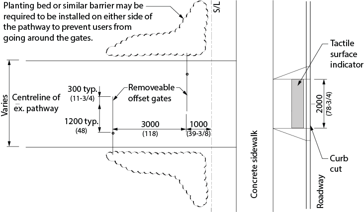
Figure 4.5.2.1 Offset Gates with Sidewalk
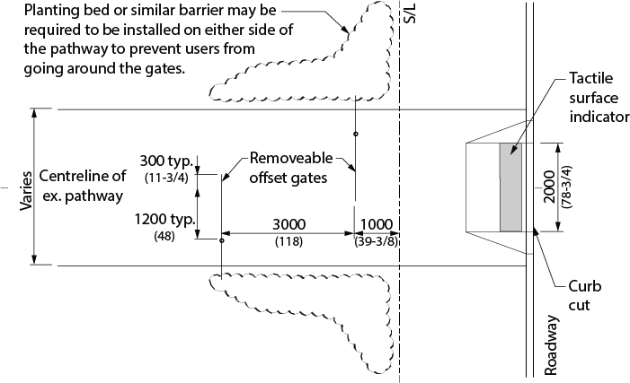
Figure 4.5.2.2 Offset Gates without Sidewalk
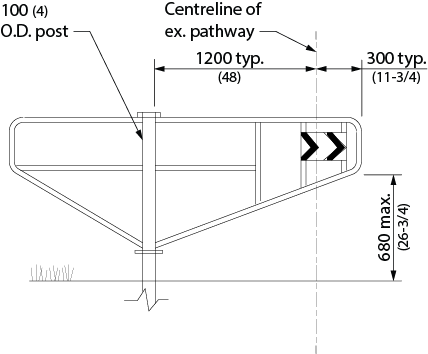
Figure 4.5.2.3 Offset Gate Elevation
Planting and Trees
- Planting and trees along accessible pathways shall comply with 4.3.14.
Rest Areas
- Rest areas shall
- be provided on recreational trails, pathways and walkways every 30 to 90 m (98 ft. - 5 in. to 295 ft. - 3 in.);
- be positioned adjacent to the recreational trail, pathway or walkway;
- have accessible ground surfaces in compliance with 4.1.2; and
- use a contrasting ground finish material to identify functional change.
- Organizations shall consult with the public including people with disabilities about the need for, location, and design of rest areas, passing areas, viewing areas, and amenities (accessible seating) along trails. Municipalities must also consult with their Accessibility Advisory Committee.
Parks - General
- Entrance gates, paths and walkways throughout the park shall be accessible to a person using a wheelchair or scooter.
- Where possible, picnic and play areas shall be provided in both sunny and shaded areas.
Playgrounds
- In addition to the requirements for Parks - General of this section, outdoor play spaces shall consist of an area that includes play equipment, such as swings, or features such as logs, rocks, sand or water, where the equipment or features are designed and placed to provide play opportunities and experiences for children and caregivers.
- Organizations shall consult on the needs of children and caregivers with various disabilities and shall do so in the following manner:
- Public sector organizations and large organizations shall consult with the public and persons with disabilities; and
- Municipalities shall also consult with their municipal accessibility advisory committees, where one has been established.
- The consultation process must address requirements for accessible play elements for children and caregivers with various disabilities including, but not limited to sensory and active play components.
- Children’s play areas and playground equipment, sandboxes or other amenities shall generally be designed to be accessible to and useable by children with varying levels of ability. Provide sufficient clearance to provide children and caregivers with various disabilities the ability to move through, in and around the outdoor play space. Colour contrast is important.
- Playground surfaces shall be firm and stable.
- Playgrounds should be designed with reference to the National Standard CAN/CSA-Z614 for "Chlildren's Play spaces and Equipment (current version).
Picnic Tables
- Accessible picnic tables shall comply with 4.3.16.
- Where public parking is provided to serve picnic facilities, accessible picnic areas should be within 30 m (100 ft.) of the accessible parking spaces.
Drinking Fountains
- Accessible drinking fountains shall comply with 4.3.1.
Public Telephones
- Accessible public telephones shall comply with 4.4.5.
Illumination (Where Provided)
- Light sources used shall be indirect, non-glare, non-flickering type and provide even levels of light distribution. (Refer also to 4.4.13.)
- No lighting is allowed in natural environments.
Washrooms
- Where washrooms are provided to support the use of outdoor recreation facilities by the general public, clients, customers, performers or staff, they shall comply with all applicable sections of 4.2.
Waterfront Areas
- Where paths and/or lookout points are provided, they shall be accessible to all individuals.
- Seating shall be provided along paths and at lookout points, in compliance with 4.3.15.
- Where parking is provided, it shall be located as close as possible to waterfront area. An accessible route shall be provided from the parking area to paths and/or lookout points (where provided).
Natural Areas
- Accessible pathways, trails and footbridges shall be provided where environmental considerations will permit.
- Paths and trails shall incorporate rest areas and where appropriate, with seating.
Grandstand and Other Viewing Areas
- Where visitor, spectator and/or participant seating is provided, accessible seating options in compliance with 4.3.2 shall be provided.
Playing Fields
- Where provided, controlled access points shall be designed to accommodate a person using a wheelchair or scooter. (e.g., Where turnstiles are used, an adjacent accessible gate shall be provided in compliance with 4.1.7.)
- Where provided, level seating areas shall be provided beside sports fields for spectators or participants with disabilities.
- Where provided, public viewing areas shall comply with 4.3.2.
- Where provided, public washrooms shall comply with 4.2.
- Where provided, public showers and change rooms shall comply with 4.2.8 and 4.3.4.
Access to Spectator Areas of Sports Fields
- Where designated spectator areas are provided at sports fields, they shall be accessible.
- Pedestrian pathways to spectator areas of sports fields shall be designed to comply with ,Recreational Trails and Footbridges requirement of this section.
Leash Free Dog Parks
- Entrance gates into dog parks shall comply with 4.1.7.
- Pedestrian pathways within leash free dog parks shall be designed to comply with the Recreational Trails and Footbridges requirement of this section.
Outlooks
- Where waste receptacles, light standards, benches and other potential obstructions or amenities are provided, they shall be located so as not to obstruct the clear path of travel.
- Where scenic outlooks have been provided they shall:
- be located on an accessible route in compliance with 4.1.4;
- incorporate smooth and stable surfaces at transition points;
- incorporate continuous edge protection, at least 100 mm (4 in.) high and of a contrasting colour around the edge of the outlook area; and
- if benches are provided they shall comply with 4.3.15.
Beach Access Routes
- Applicable to newly constructed and redeveloped beach access routes that an obligated organization intends to maintain, including permanent and temporary routes and temporary routes that are established through the use of manufactured goods, which can be removed for the winter months.
- Where beach access is constructed (not natural):
- MAX cross slope no more than 1:50;
- 1:2 bevel at height change between 6-13mm (1/4 - 1/2 in.);
- MAX running slope 1:10 at changes in level of 14-200mm (1/2 - 7-7/8 in);
- Must have a ramp that meets requirements of 4.1.9 Ramps, where change of level is greater than 200mm (7-7/8 in.).
- Where surface is not constructed, the MAX cross slope must be the minimum cross slope for drainage.
- Entrance must have a clear opening of 1000mm (39-3/8 in.) (whether the entrance includes gate, bollard, or other entrance design).
- Beach access routes must be firm and stable with openings no greater than 20 mm (3/4 in.) and oriented perpendicular to the direction of travel.
Exceptions
- Exemptions to the requirements that apply to recreational trails and beach access routes are permitted where the requirements, or some of them, would likely affect the heritage, historical, cultural or natural heritage value of an area. Rever to Part IV.1 of Ontario Regulation 191/11 (Integrated Accessibility Standards).
4.5.2 - Related Sections
All relevant parts of Sections 4.1, 4.2, 4.3 and 4.4.
4.5.3 - Swimming Pools, Therapeutic Pools/Public Spas and Spray Pads
4.5.3 - Rationale
- Swimming is an important recreational and therapeutic activity for many persons with disabilities. The buoyancy and freedom offered by an immersive water environment can be enabling in themselves. Primary considerations for accommodating persons who have mobility impairments include accessible change facilities and a means of access into the water. Ramped access into the water is preferred over lift access, as it promotes integration (everyone will use the ramp) and independence. Many persons who are visually impaired will benefit from colour and textural cues along primary routes of travel and at potentially dangerous locations, such as the edge of the pool, at steps into the pool and at railings.
- Therapeutic pools are generally smaller, shallower pools that include a ramp access and provide submerged bench seating in addition to open exercise space. The warm water in therapeutic pools is ideal for those recovering from an injury, living with chronic disease or who want to participate in a gentle but effective exercise program. The benefits of Aquatic Therapeutic exercise are:
- Warm water promotes relaxation;
- Reduced pain;
- Decreased muscle tension;
- Improved circulation;
- Increased ability and length of time for exercise; and
- Helps to maintain an independent lifestyle.
4.5.3 - Application
- In addition to the design requirements specified in 4.1 to 4.4, swimming pools, wading pools, hot pools, spray pads, therapeutic pools, and spas shall comply with this section.
4.5.3 - Design Requirements
- Swimming pools, hot pools public spas and therapy pools shall have
- where the pool is indoors,
- where the pool is outdoors,
- access from the pool deck into the water, provided by a ramp that shall have
- a handrail on either side at 865 - 965 mm (34 - 38 in.);
- a clear width of at least 1100 mm (43-1/4 in.);
- a curb or other means to prevent a wheelchair from falling off the side;
- surface finishes capable of being kept clean, sanitary and free from slipperiness;
- where ramp is not submerged it shall
- have a landing at the bottom of the ramp that is at least 450 - 550 mm (18 - 21-3/4 in.) below the top of the wall;
- be equipped with a floor drain at the lowest point;
- have a width at the top of the wall between the pool and ramp of 250 - 300 mm (10 - 11-3/4 in.);
- have water depth at the landing clearly marked in figures at least 100 mm high on the top of the wall; and
- have a maximum slope of 1:12;
- where ramp is submerged it shall
- have water depth at the bottom of the ramp of 600 - 900 mm (23-5/8 - 35-1/2 in.);
- have a hard-surfaced area that is at least 750 mm (30 in.) wide contiguous to the entire length of the submerged ramp;
- have finishes that are different in colour or shade from each other and from that of the pool walls and bottom; and
- have a maximum slope of 1:9.
- a shower chair available at each facility for use in transferring into the water and/or shower;
- where steps are provided into the pool,
- steps shall be marked with a colour-contrasting strip of at least 50 mm (2 in.) wide, at both the riser and the tread; and
- colour-contrasting handrails on both sides of the steps. Such handrails shall extend at least 300 mm (11-3/4 in.) beyond the pool edge;
- where a curbed edge is provided, it shall be a minimum of 200 mm (7-7/8 in.) and a maximum of 400 mm (15-3/4 in.) in height;
- pool boundaries clearly defined by both a textural change and a colour contrast to both the water surface and surrounding area;
- perimeter of pool deck clearly delineated by a tactile surface indicator around the pool;
- firm, slip-resistant materials and finishes used on the pool perimeter, deck or paved areas surrounding the pool;
- non-abrasive and easy-to-clean pool perimeter finishes;
- adequate drainage on the pool deck to drain water quickly;
- where pool-depth indicator marking is provided, depth- indicator markings, as well as ‘SHALLOW END’ and ‘DEEP END’ markings, of a highly contrasting colour and sufficient size to be easily visible;
- where diving boards or platforms are provided, they shall be clearly marked and protected. Overhead clearances should be a minimum of 2100 mm (82-3/4 in.) or shall be protected by suitable guards;
- where lanes, and/or lane markers are provided, they shall be of a highly contrasting colour. Tie-off devices for lane markers shall be positioned such that they do not create a tripping hazard;
- where starting blocks are provided, they shall be of a highly contrasting colour and capable of being securely fixed in place;
- safety equipment and other accessories shall be stored such that they do not present a tripping hazard; and
- lifeguard chairs, slides and other pool related structures shall be in highly contrasting colours.
- In retrofit situations where it is technically infeasible to provide a ramp, a mechanical pool lift may be used. Some pools may have both a ramp and pool lift. The pool lift has a sling lift that provides a higher level of assistance for those who may require this level of support.
- Where a mechanical pool lift is provided,
- it should not be installed where water level exceeds 1220 mm (48 in.) unless entire pool depth is more than 1220 mm (48 in.);
- the centerline of the seat should be located over the deck and a minimum 400 mm (15-3/4 in.) from the edge of the pool when in raised position;
- a clear space beside the seat opposite the water at least 915 mm (36 in.) wide and extend forward not less than 1220 mm (48 in.) from a line located 305 mm (12 in.) behind the rear edge of the seat;
- it shall be capable of unassisted operation from both deck and water levels and be unobstructed when the lift is in use; and
- shall have a weight capacity of at least 135 kg (300 lbs) and capable of static load at least 1.5 times the rated load.
- Wading pool access shall be safe and gradual so that a child with a disability can be assisted into the water easily and/or use a wheelchair to enter.
- Swimming pools shall be of ‘level-deck’ design.
Therapeutic Pools/Public Spas
- Water temperature shall be heated to between 33-34°C (92 - 94°F).
- Temperature or other controls associated with the therapy pool (such as submerged water jets) shall meet requirements in 4.4.2.
- Depth for the exercise portion of a therapy pool shall be between 1050 - 1200 mm (41 - 47 in.).
- Submerged benches shall comply with 4.3.15.
- Exercise bars (below water level) shall be incorporated into the design of a therapy pool.
- A public spa shall be surrounded by a hard-surfaced deck that
- shall have a minimum clear deck space of not less than 1800 mm (70-7/8 in.) at the main entrance point; and
- shall have a minimum clear deck space of 900 mm (35-1/2 in.) on all sides.
- Exception: where the public spa has an area of less than 6 square metres, and has no interior dimension of more than 2500mm (98-1/2 in.), one section of the pool deck that does not exceed 25% of the perimeter may have a minimum clear deck space of not more than 300 mm (11-5/8 in.)
- Where a set of steps is provide for entry into and egress from the public spa, the steps shall
- be equipped with a handrail;
- have a non-slip surface; and
- have a band of contrasting colour along the entire juncture of the side and top of the edges.
- The slope of the bottom of any portion of a public spa shall not exceed 1:12 (8%).
- The maximum depth of water to a seat or bench in a public spa shall be 600mm (23-5/8 in.)
- At least one accessible access point shall be provided into a public spa. The access point shall be a ramp in compliance with this section or a transfer wall. A transfer wall shall:
- have a height of 405 - 485 mm (16 - 19 in.) above pool deck;
- have depth between 300 and 400 mm (11-3/4 - 15-3/4 in.);
- be slip-resistant and have edges rounded;
- have minimum one grab bar
- perpendicular to pool and extending full depth of transfer wall;
- located between 100 - 150 mm (4 - 5-7/8 in.) above transfer wall; and
- with clearance of at least 610 mm (24 in.) on both sides;
- have adjacent clear deck area for lateral transfer to the transfer wall that
- is outside of and adjacent to barrier free path of travel;
- has no obstructions at side of transfer wall;
- has clear space of 900 (35-1/2 in.) x 2200 mm (86-5/8 in.); and
- has a slope less than 2% at base of transfer wall surface; and
- have adjacent clear deck area centred on the grab bar where one grab bar is provided, or centred on the clear space between grab bars where more than one is provided.
- An emergency telephone with direct connection to emergency services shall be installed within 30m (98 ft. 5 in.) of a public spa.
- All pumps in a public spa shall be capable of being deactivated by an emergency stop button that is clearly labeled and located within sight and readily accessible within 15m (49 ft. 2-1/2 in.) of persons using the public spa. The emergency stop control shall be separate from the timing device, activate an audible and visual signal when used, and be identified with emergency signage.
Spray Pads
- Spray pads shall be designed
- with an accessible route to the facility;
- to have no curb;
- to have a non-slip surface; and
- with all vertical elements to have high colour contrast with the surrounding elements and environment.
4.5.3 - Related Sections
All relevant parts of Sections 4.1, 4.2, 4.3 and 4.4.
4.5.4 - Cafeterias
4.5.4 - Rationale
- Cafeteria serving lines and seating area designs need to reflect the lower sight lines, reduced reach, knee-space and manoeuvring requirements of a person using a wheelchair or scooter. Patrons using mobility devices may not be able to hold a tray or food items while supporting themselves on canes or while manoeuvring a wheelchair. Tray slides should be designed to move trays with minimal effort.
- Features such as colour contrasts and large print menus may assist persons with vision loss/no vision.
4.5.4 - Application
- In addition to the design requirements specified in 4.1 to 4.4, cafeterias shall comply with this section.
- Where fixed tables or counters are provided, at least 10%, but not less than one, shall be accessible and shall comply with 4.3.7. It is preferable to have all fixed tables accessible.
- In new construction, and where practicable in alterations, the fixed tables (or counters) shall be distributed throughout the space.
- At least one lane at each cashier area shall be accessible and comply with this section. It is preferable to have all lanes at all cashier areas accessible.
4.5.4 - Design Requirements
- Where food or drink is served at counters exceeding 865 mm (34 in.) in height and counters are for use by customers seated on stools or standing at the counter, a minimum of 1525 mm (60 in.) length of the counter shall be constructed in compliance with 4.3.8. Service may also be made available at accessible tables within the same area.
- Access aisles at least 1100 mm (43-1/4 in.) shall be provided up to and around all accessible fixed tables. The access aisle shall be measured between parallel edges of tables or between a wall and the table edges.
- Dining areas, including raised or sunken dining areas, and outdoor seating areas shall be accessible. In a retrofit situation where it is technically infeasible to provide access to all levels within a dining area, or to all parts of outdoor seating areas, at least one dining area shall be accessible. The accessible area must feature the same level of service and décor as the rest of the dining area and it must not be restricted to use by persons with disabilities.
- A minimum of 20% of the tables must be accessible to persons using mobility aids (AODA, IASR, Design of Public Spaces).
- Access to outdoor eating areas shall comply with 4.3.11.
- Food service lines shall have a minimum clear width of 1100 mm (43-1/4 in.).
- Tray slides shall be mounted no higher than 865 mm (34 in.).
- If self-service shelves are provided, at least 50% must be within the reach ranges specified in 4.1.1. It is preferable to have all self-service shelves accessible.
- Self-service shelves and dispensing devices for tableware, dishware, condiments, food and beverages shall be installed to comply with 4.1.1.
- Cashier locations should feature at least one access aisle, which is a minimum of 1100 mm (43-1/4 in.) wide. It is preferable to have all aisles accessible.
- In banquet rooms or spaces where a head table or speaker’s lectern is located on a raised platform, the platform shall be accessible in compliance with 4.1.9 or 4.1.14, as well as 4.3.3.
- Spaces for vending machines, beverage dispensers and other equipment shall comply with 4.1.1 and shall be located on an accessible route in compliance with 4.1.4.
- Barriers and/or turnstiles, where provided to control access, shall comply with 4.1.7.
- Queuing areas shall comply with 4.3.6.
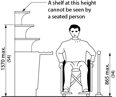
Figure 4.5.4.1 Self Serve Counter
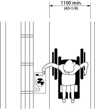
Figure 4.5.4.2 Aisle Width
4.5.4 - Related Sections
All relevant parts of Sections 4.1, 4.2, 4.3 and 4.4.
4.5.5 - Churches, Chapels and Other Places of Worship
4.5.5 - Rationale
- Access to all areas of worship should be provided. Access assumes that persons with disabilities may be participants, leaders, staff or volunteers.
4.5.5 - Application
- In addition to the design requirements specified in 4.1 to 4.4, churches, chapels and other places of worship and/or reflection shall comply with this section.
4.5.5 - Design Requirements
- All areas in churches, chapels and other places of worship and/or reflection shall be accessible to persons with disabilities, including main areas of worship, meeting rooms, washrooms, coatrooms and offices.
- Accessible seating shall be provided in compliance with 4.3.2.
- Pulpits, altars, daises and choir areas shall comply with 4.3.3.
- Public address systems shall comply with 4.4.9.
- Assistive listening systems shall comply with 4.4.6.
4.5.5 - Related Sections
All relevant parts of Sections 4.1, 4.2, 4.3 and 4.4.
4.5.6 - Libraries
4.5.6 - Rationale
- Traditional and automated systems should be available to all patrons and staff. Both the design of the facility and the provision of services should be considered. Service counters and study carrels should accommodate the knee-space and armrest requirements of a person using a wheelchair. Computer catalogues, carrels and workstations should be provided at a range of heights, to accommodate persons who are standing or sitting, as well as children of many ages and sizes. It is preferred to provide height-adjustable furnishings.
- The provision of workstations equipped with assistive technology such as large displays, screen readers, etc. will increase the accessibility of a library.
- The provision of book drop-off slots at different heights for standing and seated use will enhance usability.
4.5.6 - Application
- In addition to the design requirements specified in 4.1 to 4.4, libraries shall comply with this section.
- Where fixed seating, tables or study carrels are provided, at least 10% but no less than one shall be accessible and in compliance with this section. It is preferable to have all fixed seating, tables and study carrels accessible.
- At least one lane at each checkout area shall be accessible and comply with this section. It is preferable to have all lanes at all checkout areas accessible.
- Where computer catalogues or workstations are provided, at least 50% shall be accessible and shall comply with this section. It is preferable to have all computer catalogues and workstations accessible.
4.5.6 - Design Requirements
- Accessible fixed seating, tables and study carrels shall be located on an accessible route in compliance with 4.1.4.
- Clearances between fixed seating, tables and study carrels shall comply with 4.1.4.
- Where shelving is provided at fixed seating, tables or study carrels, the shelving shall be no higher than 1120 mm (44 in.).
- Accessible fixed study carrels shall incorporate
- work surfaces and knee/toe clearances that comply with 4.3.7;
- an electrical outlet; and
- lighting levels of at least 100 lux (9.3 ft-candles) at the work surface.
- Where provided, traffic control or book security gates shall comply with 4.1.7.
- Minimum clear aisle space at card catalogues and at stacks shall comply with 4.1.4.
- Aisle configurations shall incorporate a clear floor space allowing a person in a wheelchair to make a 180-degree turn in compliance with 4.1.1.
- Maximum reach heights at card catalogues shall comply with 4.1.1.
- Shelf height in stack areas is unrestricted.
- Circulation service counters and information service counters shall comply with 4.3.8.
- Where provided, computer catalogues and computer workstations shall incorporate
- A minimum of one movable chair shall be provided at every information service counter, computer catalogue or computer workstation.
- Book drop slots shall
- be located on an accessible route complying with 4.1.4;
- be located adjacent to a 2440 by 2440 mm (96 by 96 in.) level clear floor space. In a retrofit situation where it is technically infeasible to create a 2440 x 2440 mm (96 by 96 in.) clear floor space, the space may be reduced to 1525 x 1525 mm (60 by 60 in.); and
- have a slot that is operable using one hand, located between 860 mm (34 in.) and 1220 mm (48 in.) above the floor.
- Lighting at book stacks shall be mounted directly over the aisle space and provide a minimum of 200 lux (20 ft-candles) at a nominal working height of 920 mm (36 in.).
- The acoustic quality shall be free of unnecessary background noise and should permit comprehension by persons with limited hearing. (Refer also to 4.4.16.)
- Where CDs, tapes, talking books, etc. are available as part of the library resource materials, or for loan purposes, a separate space shall be provided for auditing this material without disturbing other library users.
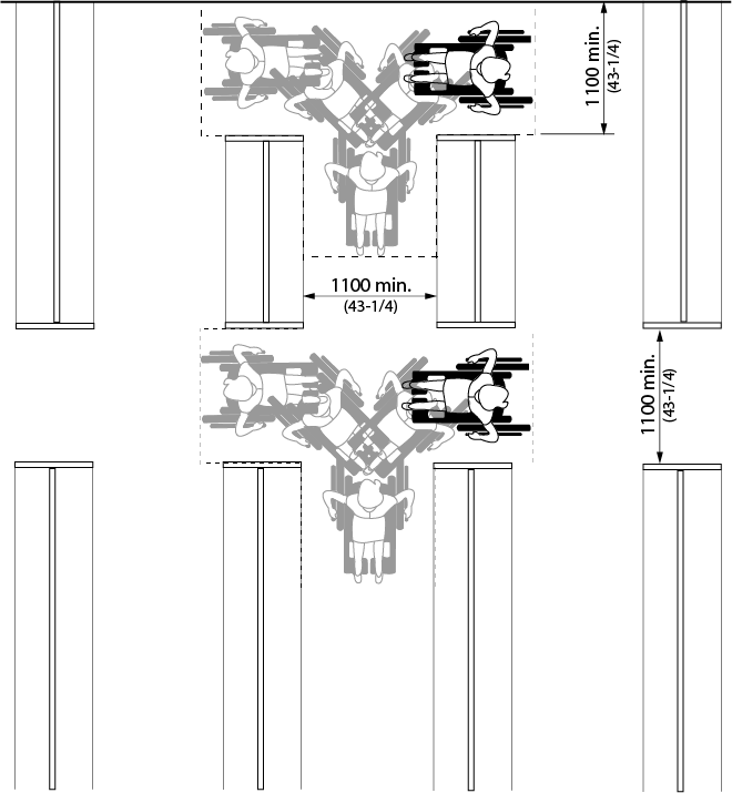
Figure 4.5.6.1 Aisle Width
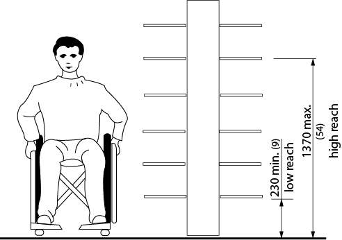
Figure 4.5.6.2 Reach Heights
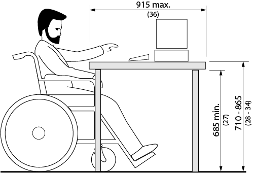
Figure 4.5.6.3 Work Surfaces
4.5.6 - Related Sections
All relevant parts of Sections 4.1, 4.2, 4.3 and 4.4.
4.5.7 - Business, Mercantile and Civic
4.5.7 - Rationale
- The role of persons with disabilities should not be restricted or limited to that of the customer or consumer. Workspaces should be designed with a view to future adaptation or accommodation of individual equipment or assistive devices.
4.5.7 - Application
- In addition to the design requirements specified in 4.1 to 4.4, business, mercantile and civic facilities shall comply with this section.
- In areas used for transactions where counters have cash registers and are provided for sales and distribution of goods or services to the public, at least one of each type shall have a portion of the counter accessible and in compliance with this section. Such counters shall include, but not be limited to, counters in retail stores and distribution centres.
- Where counters are dispersed throughout the facility, the accessible counters must also be dispersed throughout the facility.
- In public facilities where counters or teller windows have solid partitions or security glazing to separate personnel from the public, at least one of each type shall provide a method to facilitate voice communication. Such methods may include, but are not limited to, grills, slats, talk-through baffles, intercoms or telephone handset devices.
- The number of accessible checkout aisles provided shall be in conformance with Table 4.5.7.
| Total checkout aisles of each design | Minimum number of accessible checkout aisles of each design |
|---|---|
| 1 - 4 | 1 |
| 5 - 8 | 2 |
| 9 - 15 | 3 |
| Over 15 | 3 plus 20% of additional aisles |
4.5.7 - Design Requirements
- All accessible sales and service counters shall be on an accessible route that complies with 4.1.4.
- In areas used for transactions where counters have cash registers and are provided for sales and distribution of goods or services to the public, the counter shall have at least one portion that is at least 920 mm (36 in.) in length, with a maximum surface height of 865 mm (34 in.) above the finished floor and shall have adjacent clear floor space of at least 1370 mm x 810 mm (54 x 32 in.) to allow for parallel approach by a person using a wheelchair or scooter.
- In areas used for transactions that may not have a cash register but at which goods and services are sold, including, but not limited to, ticketing counters, teller stations, registration counters, information counters, box office counters and library check-out areas either a portion of the main counter shall be a minimum of 865 mm (34 in.) in length, with a maximum height of 865 mm (34 in.) or an auxiliary counter with the required minimum dimensions shall be provided in close proximity to the main counter.
- In public facilities where counters or teller windows have solid partitions or security glazing to separate personnel from the public, the method of communication provided shall be accessible to both individuals who use a wheelchair or scooter and individuals who have difficulty bending.
- The clear width of accessible checkout lines shall comply with 4.1.4, and the maximum adjoining counter height shall not exceed 965 mm (38 in.) above the finished floor. The top of any counter edge protection shall be no more than 50 mm (2 in.) above the top of the counter surface on the aisle side of the check-out counter.
- Signage identifying accessible checkout aisles shall incorporate the International Symbol of Access and shall be mounted above the checkout aisle in the same location where the checkout number or type of checkout is displayed.
- Any devices used to prevent the removal of shopping carts from store premises shall not prevent access or egress to persons who use a wheelchair or scooter. An alternate entrance that is equally convenient to that provided for ambulatory persons is acceptable.
4.5.7 - Related Sections
All relevant parts of Sections 4.1, 4.2, 4.3 and 4.4.
4.5.8 - Fire Stations
4.5.8 - Rationale
- Municipal fire stations should accommodate the accessibility needs of potential facility users (while supervised), including but not limited to:
- Injured staff attending a Captain’s office or other meeting space within the facility;
- Administration staff, Council Members, Consultants, etc attending site visits;
- Tours of non-work staff (School groups, etc.);
- Occasional uses of the facility. Fire stations contain spaces that may be used by the public while supervised by staff;
- Use by members of the general public in an emergency situation; and
- Pedestrian walk-up and/or vehicular drop-in requests for assistance/emergency services.
- Areas of fire stations likely to be used by the public, including the apparatus bay, should be accessible for persons with disabilities.
4.5.8- Application
- Areas of a fire station that are accessible to the public and/or intended for access/viewing by visitors shall comply with this section.
- Exception: Facilities for the exclusive use of firefighters such as hose towers, fitness rooms, 2nd floors, dormitories, and any basement level storage space.
- At least one accessible public washroom shall be provided.
4.5.8 - Design Requirements
- Public entrances shall be accessible and in compliance with 4.1.5.
- Firefighter entrances shall be accessible and in compliance with 4.1.5, except that a power door operator is not required, unless it is required by the Ontario Building Code.
- An accessible path of travel in compliance with 4.1.4 shall be provided from accessible public entrances to all spaces that are accessible to the public or intended for access/viewing by visitors.
- Where more than 3 entrances are provided, minimum 2 barrier-free entrances are required (per OBC).
- Spaces that may be used by community and public within fire stations shall comply with Section 4.3.5.
- Common-use areas within a fire station, such as the kitchen, shall comply with all relevant sections of this Standard.
- The accessible washroom shall:
- comply with 4.2.7 except that an adult-sized change table is not required (but space for an adult sized change table must be provided); and
- have a baby change table.
- Where public parking is provided, at least one accessible parking space shall be located close to the primary public entrance.
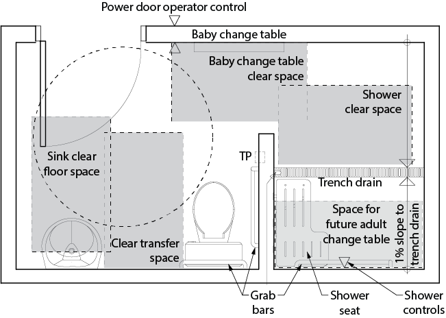
Figure 4.5.8.1 Universal Washroom - Renovation
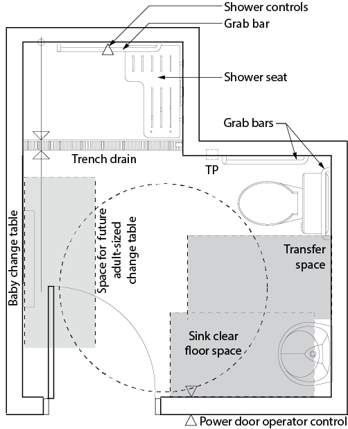
Figure 4.5.8.2 Universal Washroom - New Construction
4.5.8 - Related Sections
All relevant parts of Sections 4.1, 4.2, 4.3 and 4.4.
4.5.9 - Training and Teaching Spaces
4.5.9 - Rationale
- Students, teachers and staff with disabilities should be accommodated in all training and teaching spaces throughout the facility. Basic accommodation includes the ability to enter and move freely throughout the space, as well as use the various built-in elements within (i.e. integrated technology, whiteboards, switches, computer stations, sinks, etc.)
- Individuals with disabilities frequently use learning aids and other assistive devices that require a power supply. The provision of additional electrical outlets throughout training and teaching spaces will better-accommodate the use of such equipment.
- Where built-in elements are duplicated within individual training/teaching spaces, such as laboratory benches or pin boards, at least one of each type of element should be accessible.
- Fixtures, fittings, furniture and equipment specified for training/teaching spaces, shall be flexible for use by students, teachers and staff with a wide range of abilities. Adjustable height tables and chairs, removable armrests and including rolling/locking casters on furniture allows an individual to make any adjustments needed to adapt the environment to meet their individual needs.
4.5.9 - Application
- All training and teaching spaces shall be accessible and shall comply with this section.
- Where built-in elements such as fixed seating, tables or laboratory benches are provided within a training/teaching space, at least 10% but no less than one, shall be accessible and in compliance within this section.
- At least 2% of the seating shall be wider seats with a load capacity of at least 227 kg (500 lbs).
- At least 2% of tables and chairs shall be height adjustable.
- At least 50% of shelf space in storage facilities in training/teaching spaces shall comply with this section.
- Where writing surfaces are integrated into training/teaching space seating, 10% but no less than one shall accommodate persons who are left-handed.
- Classroom 'portables' shall comply with this section.
- At least 3% of the seating capacity within any training and teaching facilities shall be accessible and reserved for persons in wheelchairs.
- The common-use areas of training/teaching facilities shall comply with all relevant sections of this manual.
4.5.9 - Design Requirements
- Training and teaching spaces shall incorporate
- At least one entry/egress door in compliance with 4.1.6;
- Entrance doors into training and teaching spaces with a capacity of over 60 people shall incorporate a power door operator;
- Floor surfaces throughout in compliance with 4.1.2;
- Primary circulation routes in compliance with 4.1.4, linking all functional areas and elements within the space;
- Secondary circulation routes no less than 920 mm (36 in.) wide;
- Controls and operating mechanisms in compliance with 4.4.2;
- Where provided, windows, glazed screens and sidelights in compliance with 4.1.8;
- Access to assistive learning devices such as screen reading software or adapted keyboards on an as-needed basis; and
- Access to an accessible washroom on the same floor level.
- Classrooms, auditoria, assembly areas and other training and teaching spaces that incorporate fixed seating shall
- Incorporate no less than two separate accessible seating locations;
- Incorporate accessible seating locations in compliance with 4.3.2; and
- Allow persons with disabilities to access the primary presentation area.
- Wheelchair seating spaces shall be placed in close proximity to the room entrance. The minimum size of a wheelchair seating space shall comply with 4.3.2 Viewing Positions.
- Where applicable, training and teaching spaces shall incorporate assistive listening systems in compliance with 4.4.6.
- Where training and teaching spaces incorporate safety equipment such as fire extinguishers, eye-baths or deluge shower, such equipment shall be accessible to and usable by persons with disabilities.
- Accessible work surfaces and other built-in elements within training and teaching spaces shall
- Comply with 4.3.7;
- Where applicable, incorporate controls and operating mechanisms in compliance with 4.4.2;
- Provide access to data and electrical outlets within close proximity and easy reach to accessible seating spaces; and
- Be positioned such that a personal assistant, service animal and/or extra equipment can be accommodated at each accessible seating location.
- Work surfaces shall incorporate non-glare finishes.
- Accessible storage elements within training and teaching spaces shall
- Where pin boards, whiteboards, smartboards or other display systems are provided within training and teaching spaces, at least one of each type shall
- Be located on an accessible route with adjacent clear floor space in compliance with 4.1.1; and
- Have its lowest edge located no higher than 760 mm (30 in.).
- Where training and teaching spaces incorporate demonstration areas such as laboratory benches, cooking prep stations, fume cabinets or computer stations, provisions must be made to facilitate viewing from a variety of eye-levels. The installation of mirrors over the demonstration areas is one way to provide such access as well as the use of cameras and a monitor screen for image display.
- Where training and teaching spaces incorporate sinks, at least one shall comply with 4.3.18.
- Where training and teaching spaces incorporate appliances such as dishwashers, ranges and/or cooktops, ovens and refrigerators/freezers, at least one of each type shall comply with 4.3.18.
- Where training and teaching spaces incorporate kitchens, each kitchen shall
- Comply with 4.3.18;
- Incorporate at least one work surface minimum 920 mm (36 in.) wide, located maximum 865 mm (34 in.) high, with knee space below at least 810 mm (32 in.) wide, 480 mm (18-7/8 in.) deep, and 685 mm (27 in.) high; and
- Alternatively, provide height adjustable work surfaces.
- Where provided, lockers shall comply with 4.3.10.
- Where speaker podiums are provided they shall comply with 4.3.7.
- Spaces intended for general training, teaching and study shall feature a background noise level no higher than 30 dB(A).
- Lighting levels in training and teaching spaces should be a minimum of 500 lux (50 f) and 750 lux (75 fc) at the podium.
- Where training and teaching spaces are intended primarily for the use of children (such as a childrens' area in a library), spaces and elements shall be designed to meet the alternate mounting height and reach range accommodating children identified in Table 4.5.9.
| Forward or Side Reach | Ages 3 - 4 | Ages 5 - 8 | Ages 9 - 12 |
|---|---|---|---|
| High (maximum) |
915 mm (36) |
1015 mm (40) |
1120 mm (44) |
| Low (minimum) |
510 mm (20) |
455 mm (18) |
405 mm (16) |
| Children over the age of 12 have the same reach requirements as adults. | |||
4.5.9 - Related Sections
All relevant parts of Sections 4.1, 4.2, 4.3 and 4.4.
4.5.10 - Laboratories
4.5.10 - Rationale
- Staff with disabilities should have equitable access to laboratory facilities.
- Basic accommodation includes the ability to enter and move freely throughout the space, as well as use the various built-in elements within (i.e. blackboards, switches, benches, sinks, etc). Individual staff with a disability may require additional accommodations beyond those identified within this section.
- Where built-in elements are duplicated within a laboratory, such as benches or pin boards, at least one of each type of element should be accessible.
- Fixtures, fittings, furniture and equipment specified for laboratories, shall be flexible for use by persons with disabilities. However, it is recognized that not all equipment found in laboratories is usable by persons with disabilities.
4.5.10 - Application
- All laboratories shall be accessible and shall comply with this section.
- Where built-in elements such as fixed seating, tables, benches or fume hoods are provided within a laboratory, at least 3% but no less than one, shall be accessible and in compliance with this section.
- At least 50% of shelf space in storage facilities in laboratories shall comply with this section.
4.5.10 - Design Requirements
- Laboratories shall incorporate
- At least one entry/egress door in compliance with 4.1.6;
- Entrance doors into laboratory spaces with a capacity of over 60 people shall incorporate a power door operator;
- Floor surfaces throughout in compliance with 4.1.2;
- Primary circulation routes in compliance with 4.1.4, linking all functional areas and elements within the space;
- Secondary circulation routes no less than 920 mm (36 in.) wide;
- Controls and operating mechanisms in compliance with 4.4.2; and
- Where provided, windows, glazed screens and sidelights in compliance with 4.1.8.
- Accessible built-in elements such as tables and benches shall
- Have work surfaces in compliance with section 4.3.7;
- Provide access to data and electrical outlets within close proximity and easy reach to accessible seating spaces; and
- Be positioned such that a personal assistant, service animal and/or extra equipment can be accommodated at each accessible seating location.
- Work surfaces shall incorporate non-glare finishes.
- Wherever practical, controls and operating mechanism associated with built-in elements and equipment shall be mounted on the front face of the built-in element or equipment, or in an equivalent location that is reachable by a user in a seated position. All other characteristics of controls and operating mechanisms shall comply with 4.4.2.
- Areas intended for demonstration purposes, such as laboratory benches, fume cabinets or computer stations, provisions must be made to facilitate viewing from a variety of eye levels. The installation of mirrors over the demonstration area is one way to provide such access.
- Where laboratory sinks are provided, at least one of each type shall comply with 4.3.18.
- Accessible storage elements shall
- Safety equipment such as fire extinguishers, eye-baths or deluge showers shall be accessible to and useable by persons with disabilities.
- Where pin boards, whiteboards, smartboards or other display systems are provided within laboratories, at least one of each type shall
- Be located on an accessible route with adjacent clear floor space in compliance with 4.1.1; and
- Have its lowest edge located no higher than 750 mm (29-1/2 in.).
- Where provided, all fume hoods shall have base surface mounted no higher than 865 mm (34 in.) above the floor. At least one fume hood shall have knee-space below, at least 685 mm high (27 in.) by 480 mm deep (18-7/8 in.) by 810 mm wide (32 in.).
4.5.10 - Related Sections
All relevant parts of Sections 4.1, 4.2, 4.3 and 4.4.
4.5.11 - Child Care/Minding
4.5.11 - Rationale
- Access to all areas within the daycare should be provided. Access assumes that persons with disabilities may be children, parents, staff or volunteers.
4.5.11 - Application
- In addition to the design requirements specified in 4.1 to 4.4, daycare centres and daycare facilities shall comply with this section. All areas in daycare centres and daycare facilities shall be accessible to persons with disabilities.
4.5.11 - Design Requirements
- The entry vestibules shall be large enough to accommodate a triple stroller and a person, in addition to the free space required for the clear swing of any door that enters the space.
- Accessible tables, counters, work surfaces and activity counters or built-in millwork shall be located on an accessible route complying with 4.1.4.
- Public address systems shall comply with 4.4.9.
- Assistive listening systems shall comply with 4.4.6.
- Kitchens/kitchenettes or Food preparation areas shall comply with 4.3.18.
- Cubbies and Coat storage areas shall comply with 4.3.9.
- If a lockable mail box is provided it shall comply with 4.4.2.
- If a separate dedicated child or infant sleeping room is provided it shall comply with path of travel and turn circle to all cots and transfer space for children with disabilities for at least 5% (never less than 1) of the beds/cots.
- Adjacencies for rooms shall have the entry and community lobby with access to a universal washroom, the main circulation corridor, an elevator (if on more than one level), a stroller storage area and access to the outdoor play space door
- Barrier-free power operators should not allow children to leave the centre unsupervised. Keypad access, card reader or other type of secure access should be incorporated and operate so that the automatic door operator only activates their use.
- Where stairs and ramps are provided, handrails shall comply with 4.1.12 and a second child-height handrail mounted at 510 – 710 mm (20 – 28 inch) will be provided.
- Where elevators are provided they shall be sized to accommodate a triple stroller and the appropriate staff-to-child ratio based on age group served by the daycare facility.
- Playgrounds on site shall comply with the CAN/CSA Z614-07 Annex H.
4.5.11 - Related Sections
All relevant parts of Sections 4.1, 4.2, 4.3 and 4.4.
4.6 - Maintenance and Operations
4.6 - Rationale
- Property maintenance is important to ensure an accessible environment that is safe and useable by everyone. Such maintenance involves the proper care, cleaning and repair of a facility, maintaining it in good order and safe condition. Snow and ice removal are particularly important components of property maintenance. Consideration should be given to the use of radiant heating at accessible entrances, ramps and other exterior elements, in an effort to maintain an optimum level of safety and continued use of accessible building elements.
4.6 - Application
- All accessible facilities, accessible elements and systems within those facilities, and contained within the facility site, shall be maintained on a regular basis to ensure their continued usability and safety.
4.6 - Maintenance Requirements
- Accessible routes and emergency exits/areas of rescue assistance shall be maintained, and kept free of objects, debris, snow, ice and/or excessive water accumulation. Maintenance shall include, but not be limited to, the timely removal of snow, ice, winter sand/salt, wet leaves and other debris from accessible routes, curb ramps, stairs, and entrances.
- Designated areas for snow piling shall be provided at pedestrian routes, entrances, stairs, ramps and public parking areas. Snow storage shall not reduce the minimum width required for an exterior accessible route, or affect the usability of accessible facilities, elements or systems.
- Catch basins and run-offs shall be kept clear to ensure rapid removal of water from melting snow or ice from all pedestrian routes.
- Regular and systematic checks shall be undertaken to ensure that no obstacles have been located in pedestrian routes (e.g., newspaper vending machines and bicycle racks or garbage containers).
- Where accessible routes are not cleared regularly, appropriate signage shall be used.
- Garbage containers shall be emptied regularly to avoid the accumulation of extraneous garbage around the containers and the likelihood of bees/insects accumulating during warmer weather.
- Light bulbs along pedestrian routes shall be replaced on a regular schedule, with lamps (of the same wattage) for which they were designed.
- Operable elements installed on or adjacent to accessible interior and exterior routes shall be inspected, well maintained on a regular schedule, and kept in operable condition. These elements can include but are not limited to:
- Elevating devices;
- Power door operators;
- Swipe card access systems;
- Signage;
- Lighting;
- Controls;
- Gates;
- Closers;
- Mechanical chair lifts;
- Automatic ticket machines; and
- Other essential equipment.
- When a portion of an accessible route is temporarily closed to users, a continuous alternative accessible route that complies with 4.1.4 (Accessible Routes, Paths and Corridors) shall be provided. The alternative accessible route shall be separated from vehicular routes, and the location and direction of the alternative accessible route shall be clear and easy to detect for individuals of all abilities. Provide Alternate Route signage including end date of disruption to be installed in compliance with 4.4.7.
- Where maintenance work is contemplated/underway clear notification must be posted to inform all users of alternate routes to accessible features such as washrooms, ramps, TTY services, escalators, elevators and other systems provided to accommodate the needs of people with disabilities. Notification signs should not only be located and maintained at the maintenance sites but also at all facility entrances, receptions, and service counters. It is also important to ensure that posted notification signs are well-maintained and provide advanced notice of disruption in service.
Appendices
Appendix A - Universal Design Principles and Guidelines
Version 2.0 - 4/1/97
Compiled by advocates of universal design, listed in alphabetical order: Bettye Rose Connell, Mike Jones, Ron Mace, Jim Mueller, Abir Mullick, Elaine Ostroff, Jon Sanford, Ed Steinfeld, Molly Story, and Gregg Vanderheiden
Major funding provided by: The National Institute on Disability and Rehabilitation Research, U.S. Department of Education
http://www.ncsu.edu/ncsu/design/cud/pubs_p/docs/poster.pdf
Copyright 1997 NC State University, The Center for Universal Design
Universal Design:
The design of products and environments to be usable by all people, to the greatest extent possible, without the need for adaptation or specialized design.
The authors, a working group of architects, product designers, engineers and environmental design researchers, collaborated to establish the following Principles of Universal Design to guide a wide range of design disciplines, including environments, products, and communications. These seven principles may be applied to evaluate existing designs, guide the design process and educate both designers and consumers about the characteristics of more usable products and environments.
The Principles of Universal Design are presented here, in the following format: name of the principle, intended to be a concise and easily remembered statement of the key concept embodied in the principle; definition of the principle, a brief description of the principle’s primary directive for design; and guidelines, a list of the key elements that should be present in a design which adheres to the principle. (Note: all guidelines may not be relevant to all designs.)
Principle One: Equitable Use
The design is useful and marketable to people with diverse abilities.
Guidelines:
1a. Provide the same means of use for all users: identical whenever possible; equivalent when not.
1b. Avoid segregating or stigmatizing any users.
1c. Provisions for privacy, security, and safety should be equally available to all users.
1d. Make the design appealing to all users.
Principle Two: Flexibility in Use
The design accommodates a wide range of individual preferences and abilities.
Guidelines:
2a. Provide choice in methods of use.
2b. Accommodate right- or left-handed access and use.
2c. Facilitate the user’s accuracy and precision.
2d. Provide adaptability to the user’s pace.
Principle Three: Simple and Intuitive Use
Use of the design is easy to understand, regardless of the user’s experience, knowledge, language skills, or current concentration level.
Guidelines:
3a. Eliminate unnecessary complexity.
3b. Be consistent with user expectations and intuition.
3c. Accommodate a wide range of literacy and language skills.
3d. Arrange information consistent with its importance.
3e. Provide effective prompting and feedback during and after task completion.
Principle Four: Perceptible Information
The design communicates necessary information effectively to the user, regardless of ambient conditions or the user’s sensory abilities.
Guidelines:
4a. Use different modes (pictorial, verbal, tactile) for redundant presentation of essential information.
4b. Provide adequate contrast between essential information and its surroundings.
4c. Maximize “legibility” of essential information.
4d. Differentiate elements in ways that can be described (i.e., make it easy to give instructions or directions).
4e. Provide compatibility with a variety of techniques or devices used by people with sensory limitations.
Principle Five: Tolerance for Error
The design minimizes hazards and the adverse consequences of accidental or unintended actions.
Guidelines:
5a. Arrange elements to minimize hazards and errors: most used elements, most accessible; hazardous elements eliminated, isolated, or shielded.
5b. Provide warnings of hazards and errors.
5c. Provide fail-safe features.
5d. Discourage unconscious action in tasks that require vigilance.
Principle Six: Low Physical Effort
The design can be used efficiently and comfortably and with a minimum of fatigue.
Guidelines:
6a. Allow user to maintain a neutral body position.
6b. Use reasonable operating forces.
6c. Minimize repetitive actions.
6d. Minimize sustained physical effort.
Principle Seven: Size and Space for Approach and Use
Appropriate size and space are provided for approach, reach, manipulation, and use, regardless of user’s body size, posture, or mobility.
Guidelines:
7a. Provide a clear line of sight to important elements for any seated or standing user.
7b. Make reach to all components comfortable for any seated or standing user.
7c. Accommodate variations in hand and grip size.
7d. Provide adequate space for the use of assistive devices or personal assistance.
Please note that the Principles of Universal Design address only universally usable design, while the practice of design involves more than consideration for usability. Designers must also incorporate other considerations, such as economic, engineering, cultural, gender, and environmental concerns, in their design processes. These principles offer designers guidance to better integrate features that meet the needs of as many users as possible.
Appendix B - Wayfinding
Appendix B - Wayfinding - Rationale
“Wayfinding” is a term that describes the spatial problem-solving process that a person uses to reach a destination. A mental “map” is formed of the overall setting and the desired destination. This map is based on information obtained from “orientation cues” that are available from the setting’s environment. These cues include not only signage, but also the overall spatial forms, structures, sounds, surface textures, colours, illumination levels, architectural features, etc. Tactile maps and/or recorded instructions can augment these orientation cues and enable people to find their way independently, even in complex settings. A well-designed setting can thus be spatially gratifying and simple enough for persons to “wayfind” if there are adequate, varied, and non-conflicting wayfinding cues available to the individual user.
Appropriate wayfinding ensures building users can answer the following questions:
- Where am I?
- Which way am I facing?
- Is this the route to my destination?
- Is it easy for me to find my way back and to all main public facilities?
Appendix B - Wayfinding - Design Considerations
Wayfinding shall:
- Assume all building users are first time visitors;
- Provide journey based information – Providing information at appropriate points in a journey that allow users to know where they are, where their destination is, what route they should take, how to recognize the destination and how to find their way back;
- Keep messages and strategies simple – Uncluttered, ground and floor surfaces free of confusing or apparent directional patterns, comprehensible to people with a broad range of abilities and language skills;
- One message at a time – Allow users to travel from one decision point to the next with a step by step approach to reach destination;
- Employ Universal Design Strategies – Consistency of message and terminology, Consistency in typography and colour, Consistency in placement of messages, Placement of signs is critical and takes into account anthropometrics, age of reader, use of assistive devices;
- Provide Wayfinding Maps – You are here locations on each map, located at floor directories, tactile maps, simple and schematic (eg. Principal entrance, parking areas and pay books, information/reception desk(s), public zones and common-use destinations, exits, and kiosks or self help areas);
- Signage zones – Placed consistently on each floor such as near public elevators and along public circulation routes, clear floor space minimum 1500 deep at signage and maps placed outside of the main path of travel;
- Information content – Will be organized in a logical order, use plain language and identify information such as accessible services/facilities on the premises, as well as other content appropriate to the building use and major occupancy;
- Signage locations shall indicate the accessible route from vehicular and pedestrian entry to the site to the parking and main entrance, accessible site facilities, passenger loading zones, directional signage to vertical circulation elements, information desk and washrooms;
- Elevator lobbies with floor directories, map of floor, directional signage to common destinations; Coordinate signage requirements with security needs;
- Acoustics – Sound transmission/reflection characteristics of finish materials shall aurally differentiate major and secondary paths of travel;
- Landmarks – Shall create an identity at specific decision making locations that helps to differentiate them from all other locations on the site; Shall be memorable visible and/or audible and/or scented; Include appropriate auditory cues along circulation routes and at destination points serve as useful wayfinding clues, especially for persons who rely upon hearing to orient themselves;
- Tactile direction indicators (or Guidance Tactile Warning Surface Indicators)– Shall be provided in large open floor areas, such as building entry lobbies, shopping malls or transportation terminals, to facilitate wayfinding by indicating the primary routes of travel. The TDIs shall lead from the entrance points to major destinations, such as an information or registration desk and elevator;
- Clearly defined boundaries – High colour and tonal contrast in materials in flooring shall enhance defining such as the junction between walls and floors, doorway recesses and corridor intersections;
- Visual characterizations – Regions or departments shall use some form of different visual characterization to define each as distinct from other areas;
- Another creative example is to use different coloured footprints to indicate the path to different sections in a building;
- Handrails – Provide along major corridors, all stairs and ramps to serve as a visual and tactile wayfinding guides as well as to help maintain balance, and prevent falls. Braille in-sets may be provided on the surface of handrails where they end at landings or open spaces that identify the users locations;
- Lighting – Provided to delineate the pedestrian route, as well as to emphasize building features, such as entrances, stairs, ramps, or signage; and
- Google indoor maps can be investigated and implemented for select public facilities.
Appendix B - Wayfinding - References
CSA B651-12
Arthur, Paul, and Passini, Romedi. Wayfinding: People, Signs and Architecture. New York: McGraw-Hill, 1992.
Passini, Romedi. Wayfinding in Architecture. New York: Van Nostrand Reinhold, 1984. (Part of the Environmental Design Series #4.)
Sleeth, Jane. Way finding takes accessibility to the next level. Canadian Occupational Safety Magazine. http://www.cos-mag.com/Human-Resources/HR-Columns/way-finding-takes-accessibility-to-the-next-level.html. 16 February 2012. Accessed 06 November 2014
Hanson + Jung Architects Inc., Wayfinding Signage Standard for Ontario Government Facilities, Ontario Realty Corporation, 18 December 2009.
Appendix B - Wayfinding - Related Sections
All relevant parts of Sections 4.1. 4.2, 4.3. and 4.4.
Appendix C - Accessibility Standards Checklist
Appendix C - Accessibility Design Standards Checklist
| Town of Aurora Facilities Accessibility Design Standards Design Development and Assessment Checklist | ||
|---|---|---|
|
Date:
Facility Name: Facility Address: F&PM Client: Group/Client: Contact: Project Description: |
Check one for each category | Comments |
|
Design Development ☐
Facility Assessment ☐ |
||
|
New Construction ☐
Renovation ☐ Exterior Only ☐ |
||
|
The Town of Aurora Accessibility Design Standards document is a design aid applicable to the design and construction of new facilities, as well as the retrofit, alteration or addition to existing facilities owned, leased or operated by the Town of Auroroa. The Design Development and Assessment Checklist has been created to assist staff, designers and contracted consultants with the application of the Accessibility Design Standards and ensure each element has been applied to each project and to document elements of a project which may have been technically infeasible to implement. In a retrofit situation where a design element has little likelihood of being accomplished due to structural conditions or other existing physical or site constraints prohibit modification, the Technically Infeasible Element Form is to be completed and signed by the Facilities and Property Management Division Manager and maintained in the project file. Where an equivalent means of facilitation is being proposed to achieve the intent of part of the Standards, an Equivalent Facilitation Proposal Form is to be completed by the designer and forwarded to the Town of Aurora Project Manager and Accessibility Coordinator. This Checklist is a reference tool only and must be used in conjunction with the Accessibility Design Standards document. It does NOT include all requirements or exceptions applicable to each design element. Staff and the prime consultant where applicable, shall complete this checklist during the design phase of each project. Checklists are to be signed by the appropriate manager and maintained in the project file. |
||
| Section | Element | Key Design Requirements | Yes | Not | Comments or N/A | |
|---|---|---|---|---|---|---|
| General Characteristics | ||||||
|
4.1.1
|
Space and Reach Requirements
|
2440 (96) turning space for wheelchairs/scooters; 1370 x 810 (54 x 32) footprint for wheelchairs and scooters; 400 - 1200 (15-3/4 - 47) forward reach range from seated position; 230 - 1370 (9 - 5) side reach range from seated position.
|
☐ | ☐ | ||
|
4.1.2
|
Ground and Floor Surfaces
|
Level changes: Up to 6 (1/4) may be vertical; 6.1 - 13 (9/32 – 1/2) to be bevelled; over 13 (1/2) to be ramp or curb ramp. Gratings max 13 (1/2) openings, perpendicular to direction of travel.
|
☐ | ☐ | ||
|
4.1.3
|
Protruding and Overhead Objects
|
Objects projecting more than 100 (4) to be cane-detectable – lowest edge no higher than 680 (26-3/4). Min 2100 (82-3/4) headroom.
|
☐ | ☐ | ||
|
4.1.4
|
Accessible Routes, Paths and Corridors
|
Wherever possible, all routes to be accessible; 1500 (59) min width for exterior routes; 1100 (43-1/4) min width for interior routes; routes less than 1830 (72) wide to have passing places no more than 30 metres (98 feet 5 inches) apart; routes less than 2000 (78-3/4) wide to have turn space at dead ends; rest areas required every 30 metres (98 feet 5 inches); edge protection may be required; slope no steeper than 1:25 (4%), or design as ramp. Max 1:50 cross-slope.
|
☐ | ☐ | ||
|
4.1.9
|
Ramps
|
Slope must be between 1:25 (4%) and 1:20 (5%); max 9 metres (29 feet 6 inches) between landings; min 2440 x 2440 (96 x 96) landings at top and bottom; min 1670 x 2440 (65-3/4 x 96) at landings at switchbacks; min 1670 (65-3/4) long landings in straight ramps; handrails required both sides, with appropriate extensions. Intermediate handrails required on stairs wider than 2200 (86-5/8) wide.
|
☐ | ☐ | ||
|
4.1.1
|
Space and Reach Requirements
|
2440 (96) turning space for wheelchairs/scooters; 1370 x 810 (54 x 32) footprint for wheelchairs and scooters; 400 - 1200 (15-3/4 - 47) reach range from seated position
|
☐ | ☐ | ||
|
4.1.11
|
Stairs
|
Open risers must not be used; tread length 280 – 355 (11 - 14); riser height 125 - 180 (4-7/8 – 7); must have detectable warning surface at top of flights; handrails required both sides, with appropriate extensions. Intermediate handrails required on stairs wider than 2200 (86-5/8) wide.
|
☐ | ☐ | ||
|
4.1.12
|
Handrails
|
865 - 920 (34 - 36) high; colour/tonal contrast with surrounding environment.
|
☐ | ☐ | ||
|
4.3.3
|
Elevated Platforms
|
On an accessible route; Detectable warning surface min. 610 – 920 (24 - 36) deep flush to edge or drop-off.
|
☐ | ☐ | ||
|
4.3.11
|
Roof-top Patios, Balconies, Porches, Terraces and Patios
|
On an accessible route; Min. 2440 (96) deep; Thresholds shall be accessible; Surfaces shall be accessible; Railings/Guards colour contrasted to surroundings; Doors open against a side wall or rail
|
☐ | ☐ | ||
|
4.3.15
|
Benches
|
On an accessible route; Provide clear, level floor space adjacent to bench for wheelchair; Bench seat 450 - 500 (18 - 20) above the ground; arm and best rests; colour contrasted to surroundings
|
☐ | ☐ | ||
|
4.3.16
|
Public Use Eating Areas
|
Min. 20% accessible; Variety of locations in each area; On an accessible route; Knee space at the table; Surface 810 - 865 (32 - 43) high; Clearance around each table; Lighting along paths of travel and at surfaces.
|
☐ | ☐ | ||
|
4.4.7
|
Signage
|
All signage shall be accessible with san serif fonts, Arabic numbers, width-to-height ratio by viewing distance (see Table 4.4.7) and stroke-width-to-height radio; Permanent rooms/space use wall-mounted signage with tactile characters and numbers; Accessibility facilities signage shall include the International Symbol of Accessibility; Tactile signage shall be on an accessible route and mounted from 1370 – 1500 (54 – 59) to the centreline; Lighting levels measured at sign surface min. 200 lux
|
☐ | ☐ | ||
|
4.4.8
|
Detectable Warning Surfaces
|
Colour contrasted to surroundings; Slip resistant; Provided at top and entry points to all stairs (circulation and exit), curb ramps, depressed curbs, elevated platforms; Min. 920 (36) deep and full width of stair; Flat top domes or cones.
|
☐ | ☐ | ||
|
4.4.13
|
Lightings
|
Exterior: Meets Illuminating Engineering Society of North America Standards; Lighting levels measured at the ground; Pedestrian entrance min. 100 lux; Parking and passenger drop-off areas min. 30 lux; Lighting fixtures placed high enough to clear normal snow accumulation Interior: Full spectrum lighting; Evenly distributed at floor level to minimize pools of light and not create areas of shadow; elevator lobbies, washrooms and at signage min. 200 lux; Office areas min. 300 lux; Emergency lighting min. 100 lux.
|
☐ | ☐ | ||
|
4.4.14
|
Materials and Finishes
|
Exterior: Non-slip and firm; Walkways to use accessible finishes; Where wood planks used, wood laid perpendicular to path of travel; Max. joints 6 (1/4) wide and lifts 3 (1/8); Gratings/grills placed to side of pedestrian routes or so narrow openings perpendicular to path of gravel an max. 13 (1/2) Interior: Any carpeting low-level loop; Hard surfaces non-slip, non-glare and accessible; Joins max. 6 (1/4) and flush; Walls non-abrasive to 2000 (79) high
|
☐ | ☐ | ||
|
4.4.15
|
Texture and Colour
|
Exterior: Pronounced colour contrast to differentiate boundaries of objects, objects from backgrounds and enhance spatial orientation. Interior: Colour contrast to define edges (e.g. stair nosings, doors, handrails); Colour/tone define boundaries (e.g. wall to floor); Baseboard contrasted to walls and floor where monochromatic colour scheme selected; Enhance wayfinding.
|
☐ | ☐ | ||
|
4.5.3
|
Swimming Pools, Therapeutic Pools/Publis Spas and Spray Pads
|
Swimming pools, Wading pools, Hot pools, Splash pads, Spray pads, Therapeutic pools and Spas shall be accessible; Pool has direct accessible route from lobby/entrance to change rooms through to pool deck; Ramp access to water; Mechanical pool lifts; Public Spas transfer walls; Therapeutic pools water temperature, controls, depth and submerged benches.
|
☐ | ☐ | ||
| Site Characteristics | ||||||
|
4.1.10
|
Curb Ramps
|
Min 1500 (59) wide; running slope 1:50 to 1:20 (2% to 5%); 900 (35-1/2) wide flared sides; must have detectable warning surface.
|
☐ | ☐ | ||
|
4.3.12
|
Parking
|
All parking structures, underground parking and surface lots; Provide both Accessible and Limited Mobility spaces; Number of each type of space as per Table 4.3.12; Parking spaces should be joined to the building by an accessible route that does not travel behind parked vehicles or along driveways; Signage at parking spaces and directional signage to location of parking shall be accessible and not mounted on fences or building faces; Directional signage shall be provided where the accessible entrance is not obvious or distant; Public consultation required.
|
☐ | ☐ | ||
|
4.3.13
|
Passenger Loading Zones
|
At least 1 shall be accessible; Identified with accessible signage; Includes space for the driveway, a lay-by and an access aisle; Connected to an accessible route; Curb ramp or drop curb with detectable warning surface; Min. 3600 (11 feet 10 inches) vertical clearance.
|
☐ | ☐ | ||
|
4.3.14
|
Landscaping Materials and Plantings
|
Min 10% plant beds accessible where plan beds provided; Min 460 (18) high; on an accessible route; Cane-detectable curbs; No permanent guide wires; Min 2100 (83) headroom clearance
|
☐ | ☐ | ||
|
4.3.17
|
Streetscapes
|
On an accessible route; Including waste receptacles, light standards, signs, planters, mail boxes, vending machines, benches, traffic signals and utility boxes; Primary routes min. 2100 (83) wide with 300 (12) continuous indicator surface; Non-primary routes min. 1500 (59); Elements do not reduce width of accessible route; Any operating mechanisms shall be accessible and provide a clear floor area for wheelchairs and scooters in front of usable parts.
|
☐ | ☐ | ||
|
4.3.19
|
Service Animal Relief Areas
|
2On an accessible route; Provided within 30m of accessible entrance; Provide accessible garbage can and identification signage.
|
☐ | ☐ | ||
|
4.4.17
|
Pedestrian Signals
|
Provided with a locator tone distinct from walk indicator; 1500 (59) from curb edge and 1100 (43-1/4) above ground; tactile arrows aligned with direction of travel; manual and automatic activation features; audible and vibro-tactile walk indicators; 3000 (118) distance between two accessible pedestrian signals on the same corner, or installed on single post with verbal announcement for active crossing.
|
☐ | ☐ | ||
|
4.5.2
|
Outdoor Recreational Facilities
|
Accessible routes, auxiliary services, plantings; Accessible Boardwalks, Docks, Recreational Trails and Footbridges, Pathways, Rest Areas, Parks, Playgrounds, Picnic tables, Drinking Fountains, Public Telephones, Lighting, Washrooms, Waterfront Areas, Natural Areas, Grandstand/Viewing Areas, Playing Fields, Leash Free Dog Parks, Access to spectator areas of sports fields, Docks/Piers, and Outlooks as per details provided.
|
☐ | ☐ | ||
| Building Characteristics | ||||||
| Access and Circulation | ||||||
|
4.1.5
|
Entrances
|
All entrances used by staff and/or the public to be accessible.
|
☐ | ☐ | ||
|
4.1.6
|
Doors
|
Power operators required at entrances, washrooms with an accessible stall, universal washrooms, change/dressing rooms with accessible toilet/shower, and intermediate doors across primary routes. Revolving doors are not accessible. Clear ground/floor space on each side (See Table 4.1.6); min 950 (37-1/2) clear opening; doors in series to be min 1525 (60) plus width of any in-swinging door, apart; power door operator controls no closer than 600 (23-5/8) from inside corner and not less than 600 (23-5/8) and not more than 1525 (60) beyond the door swing; 1370 x 810 (54 x 32) space at power door operator controls; hardware to be accessible; colour/tonal contrast with wall.
|
☐ | ☐ | ||
|
4.1.7
|
Gates, Turnstiles and Openings
|
950 (37-1/2) min clear width.
|
☐ | ☐ | ||
|
4.1.8
|
Windows, Glazed Screens and Sidelights
|
Frameless glass doors and/or sidelights must not be used. 760 (30) max height for lowest edge of viewing windows and vision panels. Operating hardware to be accessible. Decals to be used at large expanses of glass to enhance visibility.
|
☐ | ☐ | ||
|
4.1.13
|
Elevators
|
Min 1725 x 1525 (68 x 60) cab size (2030 x 1525 (80 x 60) in high use facilities); min 950 (37-1/2) clear opening at door; handrails on all non-access walls; 1370 x 810 (54 x 32) clear floor space at hall call buttons; emergency call system with two-way communication ability which does not solely rely on voice input.
|
☐ | ☐ | ||
|
4.1.14
|
Platform Lifts
|
Platform lifts can only be used to access a performing area, comply with wheelchair viewing position dispersion requirements, an incidental space not accessible to the public with no more than 5 occupants, or raised judges benches and other raised areas in a courtroom.
|
☐ | ☐ | ||
| Washroom Facilities | ||||||
|
4.2.1
|
Toilet Facilities
|
Requirements for each public or common use toilet facility; Other toilet rooms provided for the use of occupants of specific spaces (i.e. a private toilet room for the occupant of a private office) shall be adaptable; Min 1 universal washroom in addition to any accessible public or common use toilets, provided in all public buildings and on every floor level in assembly areas where the floor incorporates common or public use washroom facilities containing four or more toilet and/or urinal fixtures; Number accessible toilet stalls; Min 5% accessible portable toilets where used.
|
☐ | ☐ | ||
|
4.2.2
|
Toilet Stalls
|
Where toilet stalls used the number of accessible toilet stalls see Table 4.2.2; Min 1 ambulatory toilet within each non-accessible washroom
|
☐ | ☐ | ||
|
4.2.3
|
Toilets
|
Height of seat; Back support; Clear transfer space; Toilet flush controls are accessible and on transfer side of the toilet at 500-900 (19-5/8 - 35-1/2) above floor; L-shaped grab bar; Rear grab bar; Drop-down grab bar; Toilet-paper dispenser below grab bar with bottom of dispenser 600 - 800 (23-5/8 - 31-1/2) above floor.
|
☐ | ☐ | ||
|
4.2.4
|
Lavatories
|
On an accessible route; Top 820 - 840 (32-1/4 - 33); Knee space; clear floor space 760 (30) wide x 1370 (54) deep with up to 480 (18-7/8 in.) under the lavatory; hot water and drain pipes insulated or temperature limited; Soap and Towel dispensers accessible; Faucets and other controls; Shelves/other projections.
|
☐ | ☐ | ||
|
4.2.5
|
Urinals
|
On an accessible route; No step in front of the fixture; Wall-mounted with elongated rim max.430 (17); Min. 345 (13-1/2) deep; Forward approach clear floor space 810 x 1370 (32 x 54) in front; Privacy screens; Grab bars; Flush controls; Number of accessible urinals.
|
☐ | ☐ | ||
|
4.2.6
|
Washroom Accessories
|
Hand-operated dispensers, hand dryers, built-in garbage receptacles, mirrors, etc. accessible; 900 - 1200 (35-1/2 - 47);Tilt mirrors shall not be used.
|
☐ | ☐ | ||
|
4.2.7
|
Universal Washroom
|
Min 1 universal washroom in addition to any accessible public use or common use toilets for all public buildings and every floor of assembly buildings otherwise see Table 4.2.1;Emergency call system; Adult change table size, surface height, adjacent clear floor space, weight capacity, on an accessible route, and accessible controls.
|
☐ | ☐ | ||
|
4.2.8
|
Showers
|
Number of accessible showers see Table 4.2.8; On an accessible route; no or bevelled threshold; Trench-style drain; Wall-mounted folding seat; L-shaped grab bar; Vertical grab bar on each end wall; Pressure equalizing or thermostatic mixing valve; Fully recessed soap holder; Accessible shower head.
|
☐ | ☐ | ||
|
4.2.9
|
Garb Bars
|
Resist a load of at least 1.3 kN (300 lb.), applied vertically or horizontally; Diameter 35 – 40 (1-3/8 - 1-9/16); free of any sharp or abrasive Elements; Colour-contrasted with surrounding environment; slip-resistant surface.
|
☐ | ☐ | ||
| Other Amenities | ||||||
|
4.3.1
|
Drinking Fountains
|
On an accessible route; Cane detectable at or below 680 mm (26-3/4 in.); If cantilevered: Min 810 x 1380 (32 x 54) clear floor space with knee and toe space to min 700 (28) at the base; If freestanding: Clear floor space for parallel approach.
|
☐ | ☐ | ||
|
4.3.2
|
Viewing Positions
|
On an accessible route without blocked egress; See Table 4.3.2 for number of required spaces; Include adaptable seating; Provide storage for wheelchairs and other mobility assistive devices; Integrate accessible locations in a distributed in a variety of admission prices; Clear level and minim 920 (36) wide x 1525 (60) deep with min. 1 companion seat beside each space.
|
☐ | ☐ | ||
|
4.3.4
|
Change/Dressing Rooms
|
On an accessible route; Private accessible dressing rooms include 180 degree turn space; Accessible dressing rooms have 180 x 18030 (32 x 72) bench with 70 (30) wide clear floor space parallel to bench; Collapsible coat hooks; Slip resistant for wet conditions for flooring and bench surfaces; Accessible mirror.
|
☐ | ☐ | ||
|
4.3.5
|
Offices, work Areas and Meeting Rooms
|
On an accessible route; Clear floor space for 180-degree turn; Min 5% but not less than 1 have height adjustable work surface where multiple workstations/meeting rooms; Assistive listening system provided where required.
|
☐ | ☐ | ||
|
4.3.6
|
Waiting and Queuing Areas
|
On an accessible route; Waiting rooms with fixed seating include min. 3% and not less than 1 clear floor spaces for assistive equipment; Queuing barriers arranged in parallel lines; Permanent queuing incorporate defined floor patters/colours/textures as wayfinding; Colour contrast provided for barriers from surrounding environment; Clear floor space where lines change direction; Guides must be cane detectable.
|
☐ | ☐ | ||
|
4.3.7
|
Tables, Counters and work Surfaces
|
Min 10% to be accessible; Should be recessed; On an accessible route; Min 810 (32) wide x 1370 (54) deep clear floor space place with max. 480 under the surface; Clear knee and toe space; Surface height 710 - 865 (28 - 34) where not adjustable; Speaking port controls and height accessible.
|
☐ | ☐ | ||
|
4.3.8
|
Information, Reception and Service Counters
|
Min 1 accessible for each type of service provided; Clearly identified by signage; Where a single queue line is provided all counters will be accessible; On an accessible route; Surface, knee and toe space see 4.3.7; Knee space provided for both staff and public sides; Speaking port controls and height accessible.
|
☐ | ☐ | ||
|
4.3.9
|
Storage, Shelving and Display Units
|
At least 1 of each type shall be accessible; Self-service unit shall be on an accessible route; Forward/parallel approach clear floor space min. 810 x 1370 (32 x 54); Cloths rods/shelves max. 1370; Collapsible coat hooks max. 1200 (47); Hardware touch latch or U-shaped pulls.
|
☐ | ☐ | ||
|
4.3.10
|
Lockers and Baggage Storage
|
2At least 10% accessible; On an accessible route; Bottom shelf min. 230 (9); Top shelf max. 1200 (47); Locker IDs should be accessible; Baggage racks/carousels surface max. 460 (18) with continuous colour-contrasting strip at edge; Access spaces min. 1370 (54) deep x 810(32) wide.
|
☐ | ☐ | ||
|
4.3.18
|
Kitchens and Kitchenettes
|
For use by staff and public; Min 50% of shelf space accessible; Pass-through kitchens; U-shaped kitchens; Storage elements; Kitchen sinks; Appliances; Colour contrast.
|
☐ | ☐ | ||
| Systems and Controls | ||||||
|
4.4.1
|
Emergency Exits, Fire Evacuation and Areas of Rescue Assistance
|
Exterior: Accessible emergency exits shall be connected to an accessible route Interior: Areas of rescue assistance on an accessible route; Each space 850 x 1370 (33-1/2 x 54) per non-ambulatory occupant; Total Areas of Rescue space see Table 4.4.1; Accessible identification signage; 2-way voice communication system.
|
☐ | ☐ | ||
|
4.4.2
|
Controls and Operating Mechanisms
|
Mounted between 400 - 1200 (8 – 47); Operable with a closed fist; Lighting at min. 100 lux; Colour contrasted from surroundings.
|
☐ | ☐ | ||
|
4.4.3
|
Vending and Ticketing Machines
|
On an accessible route; Clear floor space to access controls; Controls mounted at accessible heights; Signage on machines accessible.
|
☐ | ☐ | ||
|
4.4.4
|
Visual Alarms
|
Provided at least at restrooms, general usage areas (e.g. meeting rooms), hallways, lobbies and other common use areas; Spacing max. 15 m (50 ft.) apart; Mounted 2100 (78-3/4); Meet NFPA 72 Section 18.5.3.
|
☐ | ☐ | ||
|
4.4.5
|
Public Telephones
|
Number of public phones to be accessible see Table 4.4.5; All accessible telephones and 25% of remaining require volume controls; Controls shall be accessible and meet CSA T515; Lighting minimum 200 lux; Clear floor space for front or side approach; ID signage includes symbol of accessibility.
|
☐ | ☐ | ||
|
4.4.6
|
Assistive Listening Systems
|
To be provided in assembly areas; Accessible signage identifying listen system present; May include induction loop, infrared and FM radio frequency systems.
|
☐ | ☐ | ||
|
4.4.9
|
Public Address Systems
|
Zoned to provide information to key locations only; Minimize background noise; No continuous broadcast music; A;;-point calls for emergency only.
|
☐ | ☐ | ||
|
4.4.10
|
Information Systems
|
Including kiosks, video displays, maps, and information panels; Mounted to be usable for a person using a wheelchair or scooter; Controls shall be accessible; Clear floor space for front or side use shall be provided; Also see CSA B651.1 and B651.2 standards.
|
☐ | ☐ | ||
|
4.4.11
|
Card Access, Safety and Security Systems
|
Signals are provided in both audible and visual signals; Card-entry systems and Encoded-entry/exit systems (e.g. keypads) will be accessible; On an accessible route; Clear floor space to access controls; Controls mounted at accessible heights.
|
☐ | ☐ | ||
|
4.4.12
|
Glare and Light Sources
|
Low/no-gloss, matte, satin or honed finishes; Sun-screening systems provided where direct sunlight adversely affect lighting or create reflective glare; Light fixtures will protect users from a direct view of the bulb; Special features/key orientation elements enhanced with supplementary lighting.
|
☐ | ☐ | ||
|
4.4.16
|
Acoustics
|
Finishes do not unduly amplify occasional noises; Accessible routes in large facilities aurally differentiate major and secondary paths of travel; Public address and call systems; Meeting rooms and assembly areas.
|
☐ | ☐ | ||
| Facility-Specific Requirements | ||||||
|
4.5.1
|
Arenas, Halls and Other Indoor Recreational Facilities
|
Provide accessible seating options; Use detectable warning surfaces on stairs to access seating; Accessible route to arena/facility floor min. 950 (37-1/2) wide; Min. 10% coat hooks accessible; Staff areas to be accessible.
|
☐ | ☐ | ||
|
4.5.4
|
Cafeterias
|
Min. 10% accessible where fixed tables or counters provided; Accessible tables and counters distributed throughout design; Min. 1 cashier to be accessible; Food/drink placed and Tray slides max. 860 (34) high; Min. 1100 (43-1/4) access aisles to and around accessible tables; Dining areas to be accessible; access aisles.
|
☐ | ☐ | ||
|
4.5.5
|
Churches, Chapels and Other Places of Worship
|
All areas accessible to persons with disabilities including main areas of worship, meeting rooms, washrooms, coatrooms and offices. Accessible seating; Pulpits, altars, dais and choir areas; Public address systems; Assistive listening systems.
|
☐ | ☐ | ||
|
4.5.6
|
Libraries
|
User elements on an accessible route; Min 10% of fixed seating, tables or study carrels accessible; Min 1 of each checkout area accessible; Min 50% of computer catalogues or workstations accessible; Shelving at fixed seating, tables and study carrels max. 1120 (44); Security gates and card catalogues accessible .
|
☐ | ☐ | ||
|
4.5.7
|
Business, Mercantile and Civic
|
Min 1 every transaction counters/cash register shall be accessible and on an accessible route (see Table 4.5.7); Where counters/teller windows separate public from staff the communication device shall be accessible; Checkout lines identified with International Symbol of Access signage and provide an accessible route.
|
☐ | ☐ | ||
|
4.5.8
|
Fire Stations
|
Municipal fire stations accommodate accessibility needs of all potential facility users, including - Staff returning to light duty work; Injured staff attending a Captain’s office /Other meeting space within the facility; Administration staff, Council Members, Consultants, etc attending site visits; Tours of non-work staff (School groups, etc.); Occasional uses of the facility; Meeting spaces open to the public and used for municipal functions; and Use by members of the general public in an emergency situation.
|
☐ | ☐ | ||
|
4.5.9
|
Training and Teaching Spaces
|
Students, teachers and staff with disabilities accommodated in all training and teaching spaces throughout the facility. Basic accommodation includes ability to enter and move freely throughout the space, as well as use the various built-in elements within (i.e. integrated technology, whiteboards, switches, computer stations, sinks, etc.); Additional electrical outlets throughout; Min 1 of each type of element should be accessible; Fixtures, fittings, furniture and equipment is accessible for students, teachers and staff; Adjustable height tables and chairs, removable armrests and rolling/locking casters on furniture.
|
☐ | ☐ | ||
|
4.5.10
|
Laboratories
|
Staff with disabilities have equitable access to laboratory facilities; Basic accommodation includes ability to enter and move freely throughout the space, as well as use the various built-in elements within (i.e. blackboards, switches, benches, sinks, etc); Built-in elements, such as benches or pin boards, at least 1 of each type of element be accessible except where limited by the equipment .
|
☐ | ☐ | ||
|
4.5.11
|
Child Care/Minding
|
Access to all areas within the daycare should be provided for children, parents, staff or volunteers with disabilities; Entry vestibules large enough to accommodate a triple stroller and a person, in addition to the swing of any door; Accessible tables, counters, work surfaces and activity counters or built-in millwork shall be located on an accessible route; Public address systems; Assistive listening systems; Kitchens/kitchenettes or Food preparation areas; Cubbies and Coat storage areas; Where stairs and ramps are needed, handrails and accessible and second childheight handrail provided; Playground(s) on site comply with CAN/CSA Z614-07 Annex H.
|
☐ | ☐ | ||
|
I have utilized this Checklist as a design aid in conjunction with the Town of Aurora Accessibility Design Standards throughout the design phase of this project, or during a Facility Assessment of an existing building. Project:__________________________________ I have utilized this Checklist as a design aid in conjunction with the Town of Aurora Accessibility Design Standards throughout the design phase of this project Project: Consultant/Firm:___________________________________________ |
Appendix C - Accessibility Design Standards Checklist - Document Downloads
Link to online forms below:
Appendix C - Accessibility Design Standards Checklist - Approval Process Chart
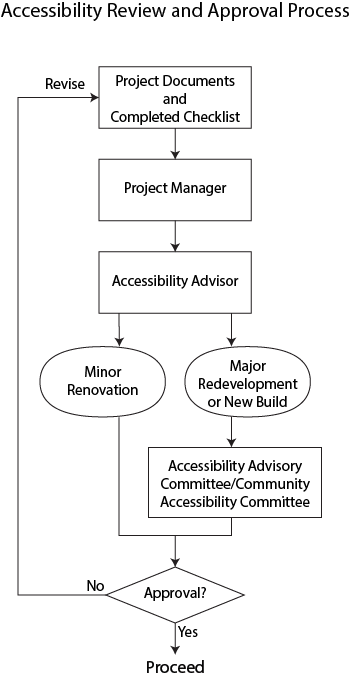
Approval Process Chart
Appendix C - Accessibility Design Standards Checklist - Accessibility Review and Approval Process
Legend:
FADS = Facility Accessibility Design Subcommittee of the AAC
AAC = Accessibility Advisory Committee
Legislation:
The AODA (Accessibility for Ontarians with Disabilities Act, 2005, Section 29) states:
Duty of the committee:
Accessibility Advisory Committee shall review in a timely manner the site plans and drawings described in section 41 of the Planning Act that the committee selects.
Duty of council:
Council shall seek advice from the committee on the accessibility for persons with disabilities to a building, structure or premises, or part of a building structure or premises,
a) that the council purchases, constructs or significantly renovates;
b) for which the council enters into a new lease; or
c) that a person provides as municipal capital facilities under an agreement entered into with the council in accordance with section 110 of the Municipal Act, 2001.
Supplying site plans:
When the committee selects site plans and drawings described in section 41 of the Planning Act to review, the council shall supply them to the committee in a timely manner for the purpose of the review.
The Integrated Accessibility Standards Regulation (O. Reg. 413/12, under the AODA) has requirements related to consulting with persons with disabilities regarding trails, playgrounds, exterior paths of travel, and on-street parking.
New Build, Redevelopment, or Renovation
- Facility planning will include accessibility in the needs assessment definition process
- RFP’s and RFQ’s include a statement that the design must comply with the FAD Standards and Checklist
- Consultants will have access to FAD Standards
- Both Project Manager and Accessibility Coordinator will discuss when a project is at the appropriate stage for FADS to review.
- Milestone Date: An Accessibility Review shall be done early enough in design phase with the Project Manager responsible for the project, the Accessibility Coordinator and FADS. It is recommended that a practice run of the presentation be made to the Accessibility Coordinator prior to presentation to FADS in order to ensure compliance with Accessibility Design Standards.
- Site review(s) during construction shall be scheduled to confirm compliance with project accessibility design features by the Project Manager and Accessibility Coordinator with the Consultant
- Should changes occur that affect accessibility features Project Manager shall consult with Accessibility Coordinator
- If requested by FADS a site visit shall be scheduled by the Project Manager and Accessibility Coordinator post construction
Minor Renovations and Capital Maintenance
All Town projects must comply with FAD Standards. Where full accessibility standards are not achievable actions must be taken to consult with the Accessibility Coordinator. Non-compliance issues will be documented in the project file.
Appendix D - Change Order
Appendix D - Change Order Form - Document Download
Link to online form below:
Appendix E - Slip Resistance of Materials
| Slip Resistance of Materials | |||
|---|---|---|---|
| Material | Slip Resistance Rating (1) | Remarks | |
| Dry and Unpolished | Wet | ||
| Cast Iron | Very Good | Very Good to Good | If open treads are used, the slip resistance can be Very Good in wet conditions. |
| Clay Tile (carborundum finish) | Very Good | Very Good | May be Good for exterior stairs. |
| Carpet (2) | Very Good | Good | |
| Clay Tiles (textured) | Very Good | Good | May be good for exterior stairs. |
| Cork Tiles | Very Good | Good | |
| Float Glass | Very Good | Poor | Various techniques can be used to modify the surface of float glass, thus improving the wet potential for slip. |
| PVC with non-slip granules | Very Good | Good | Not suitable near entrance doors. |
| PVC | Very Good | Poor to Fair | Applies to sealed, varnished or polished wood. |
| Rubber (sheets or tiles) | Very Good | Very Poor | |
| Wood (finished) | Very Good | Good | |
| Wood (unfinished) | Good | Fair | |
| Mastic Asphalt | Good | Good | |
| Ceramic Tiles (glazed or highly polished) | Good | Poor | |
| Ceramic Tiles (matte) (3) | Good | Fair to Good | Slip potential is dependent on surface roughness. A value of 10 μm is recommended for clean-water wet areas. |
| Clay Tiles | Good | Fair to Good | When surface is wet and polished it would be considered Poor. |
| Concrete Pavers (interlock) | Good | good | |
| Vinyl Tiles | Good | Fair | |
| Linoleum | Good | Poor to Fair | Edges of sheets may cause tripping if not securely fixed to base. |
| Concrete (powerfloat finish) | Good | Fair | Surface dust may cause problems especially on new floors. |
| Concrete | Good | Poor to Fair | If non-slip aggregate or a textured finish is used, slip resistance when wet may be considered Good. |
| Granolithic | Good | Poor to Fair | Slip-resistance when wet may be improved to Good by incorporating a Carborundum finish. Polished granolithic should not be used for stair treads. |
| Clay Tiles | Good | Poor to Fair | Slip-resistance when wet and polished is Very Poor. |
| Terrazzo | Good | Poor to Fair | Non-slip nosing necessary on stairs. Slip-resistance when polished is Very Poor. |
| Marble/Granite | Good | Very Poor to Fair | Slip-resistance when wet and polished is Very Poor. |
Appendix F - Additional Resources
Appendix F - Additional Resources - Documents
CNIB - Clearing our Path, Universal design recommendations for people with vision loss.
Ontario Building Code (OBC)
Accessibility for Ontarians with Disabilities Act (AODA)
Integrated Accessibility Standards Regulation (IASR)
GAATES - Illustrated Technical Guide to the Accessibility Standard for the Design of Public Spaces
Appendix F - Additional Resources - Organizations
Canadian National Institute for the Blind (CNIB)
Canadian Standards Association (CSA)
Global Alliance on Accessible Technologies and Environments (GAATES)
Technical Standards and Safety Authority (TSSA)
Transportation Association of Canada (TAC)
Ontario Recreation Facilities Association, Inc. (ORFA)
 ViewFull Town Services Menu
Contact Us